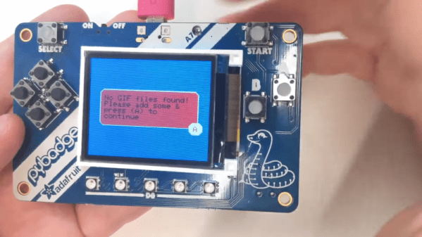
Historically, getting files on to a microcontroller device was a fraught process. You might have found yourself placing image data manually into arrays in code, or perhaps repeatedly swapping SD cards in and out. For select Arduino boards, that’s no longer a problem – thanks to the new TinyUSB library from Adafruit (Youtube link, embedded below).
The library is available on Github, and is compatible with SAMD21 and SAMD51 boards, as well as Nordic’s NRF52840. It allows the Arduino board to appear as a USB drive, and files can simply be dragged and dropped into place. The library can set up to use SPI flash, SD cards, or even internal chip memory as the storage medium.
Potential applications include images, audio files, fonts, or even configuration files. Future plans include porting the TinyUSB library to the ESP32-S2 as well. Being able to drag a settings file straight on to a board could make getting WiFi boards online much less of a hassle.
We’ve seen other nifty USB libraries before, VUSB is a great option if you need USB on your AVR microcontroller. Video after the break.
Continue reading “Drag And Drop Files On Select Arduino Boards”
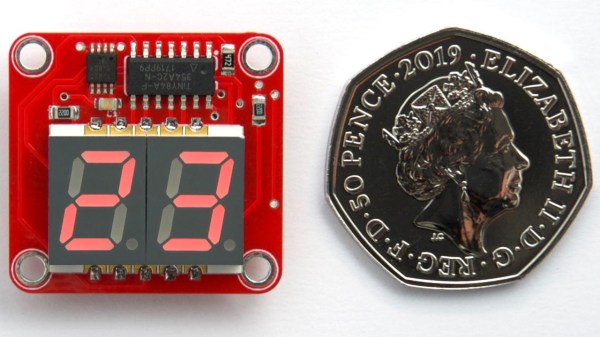
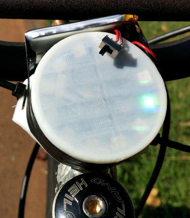
 You may think that a display that flashes only once every 24 seconds might be difficult to actually read in practice, and you’d be right. [David] found that it was indeed impractical to watch the display, waiting an unknown amount of time to read some briefly-flashed surprise numbers. To solve this problem, the decimal points flash shortly before the temperature appears. This countdown alerts the viewer to an incoming display, at the cost of a virtually negligible increase to the current consumption.

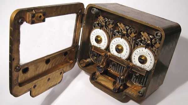
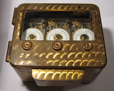 The concept of a time lock is an old one, and here you can see an example of