Enter The Matrix With This Custom PC Side Panel

With a new Matrix movie out now, it’s hardly a surprise that we’re starting to see more and more projects centered around the franchise’s iconic “Digital Rain” effect. A few particularly unique examples have floated to the top of this virtual tsunami of green-tinted sushi recipes, such as this very slick RGB LED PC side panel built by [Will Donaldson].

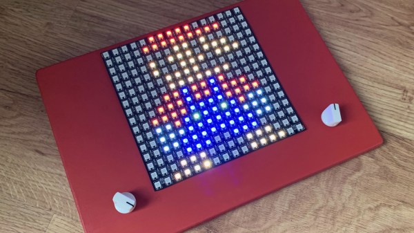
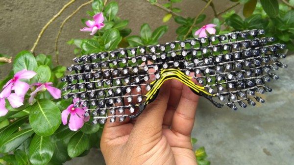
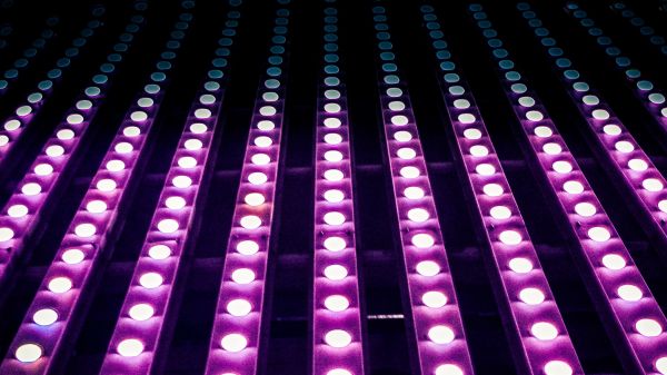
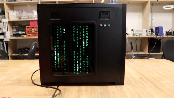
In place of the normal clear window in his PC case, [Will] has mounted a black acrylic sheet that has had all of the “code” characters laser-cut from it. Behind that is an array of WS2812B LED strips, nestled into vertically aligned channels that keep the light from bleeding out horizontally. A sheet of frosted plastic is sandwiched between the two, which helps diffuse the light so the individual LEDs aren’t as visible.

All of the LEDs are connected to a NodeMCU ESP8266 by way of a 74AHCT125 level-shifter, though [Will] notes you could certainly use a different microcontroller with some tweaks to the code. As it stands, the user selects from various lighting patterns using two potentiometers and a button that have been mounted next to the panel. But if you were so inclined, it certainly wouldn’t take much to adapt the firmware so that the lighting effects could be triggered from the PC.

The sticklers will note that this means the characters can’t actually change or move, but as you can see in the video below, it still looks quite impressive when the LEDs get going behind them. If you’re looking to recreate the look on a considerably smaller scale, check out this Arduino library that can make it rain on a TFT display with just a few lines of code.

Continue reading “Enter The Matrix With This Custom PC Side Panel”

Marble-elevator dot-matric display

Simple Design Elevates This Mechanical Dot Matrix Display

Don’t get us wrong — we love unique displays as much as anyone. But sometimes we stumble across one that’s so unique that we lack the basic vocabulary to describe it. Such is the case with this marble-raising dot-matrix alphanumeric display. But it’s pretty cool, so we’ll give it a shot.

The core — literally — of [Shinsaku Hiura]’s design is a 3D-printed cylinder with a spiral groove in its outside circumference. The cylinder rotates inside a cage with vertical bars; the bars and the grooves are sized to trap 6-mm AirSoft BBs, which are fed into the groove by a port in the stationary base of the display. BBs are fed into the groove at the right position to form characters, which move upwards as the cylinder rotates. Just watch the video below — it explains it far better than words can.

The clever bit is how the BBs are fed into the groove. Rather than have a separate mechanism to gate the feed port, there’s a backlash mechanism that opens the port when the motor powering the drum runs in reverse for a bit. It’s a clever use of cams to get the job done without adding an extra servo, which sort of reminds us of the design parsimony exhibited in his one-servo seven-segment display.

It’s not clear that this would be a very practical display, but that doesn’t stop it from being cool. Although, [Shinsaku Hiura] just released a follow-up video showing a bigger version of this used to display upcoming events from Google Calendar, so perhaps we’re wrong. Continue reading “Simple Design Elevates This Mechanical Dot Matrix Display”

LED Matrix Hourglass Knows Which Way Is Up

[Fearless Night]’s slick dual hourglass doesn’t just simulate sand with LEDs, it also emulates the effects of gravity on those simulated particles and offers a few different mode options.

The unit uses an Arduino (with ATMEGA328P) and an MPU-6050 accelerometer breakout board to sense orientation and movement, and the rest is just a matter of software. Both the Arduino and the MPU-6050 board are readily available and not particularly expensive, and the LED matrix displays are just 8×8 arrays of red/green LEDs, each driven by a HT16K33 LED controller IC.

The enclosure and stand are both 3D-printed, and a PCB not only mounts the components but also serves as a top cover, with the silkscreen layer of the PCB making for some handy labels. It’s a clever way to make the PCB pull double-duty, which is a technique [Fearless Night] also used on their earlier optical theremin design.

Those looking to make one of their own will find all the design files and source code handily available from the project page. It might not be able to tell time in the classical sense, but seeing the hourglass displays react to the device’s orientation is a really neat effect.

Minimalist Timer Counts Down With LED Matrix

Looking for something with a bit more style than the traditional kitchen timer, [Martin Jonasson] decided to take the last couple of months to design and build his own take on the idea using a rotary encoder, 16×9 LED matrix, and a Teensy 2.0 microcontroller. Were there better things he could have spent that time on? Possibly. But you probably wouldn’t have been reading it about it here, so we won’t trouble ourselves with such thoughts.

Put together on a piece of perfboard, the handwired circuit also includes an Adafruit PowerBoost 500 Charger, a 3.7 V 2500 mAh LiPo battery, a IS31FL3731 Charlieplexed PWM LED driver, and a piezo buzzer. The top of the rotary encoder has been capped off with a sold metal knob, which combined with the enclosure made of stacked laser cut 3 mm acrylic sheets, really gives the device a very sleek and classy look.

While the hardware is quite nice, it’s the software that really pulls this whole project together. A game developer by trade, [Martin] went all in on the timer’s GPLv3 licensed firmware. From using the toneAC library to play melodies at the end of the countdown, to the custom fonts and the code that pauses the timer while the user is spinning the knob, there’s plenty of little touches that should make the timer a joy to use. We’ve seen some unique kitchen timers over the years, but the attention to detail put into this build really raises the bar.

[Martin] has provided everything you need to create your own version of his timer, including the SVG file for the laser cut case. While not strictly required, coming up with a custom PCB for this project would be a nice touch, should you want to put your own spin on it.

[Thanks to Tom for the tip.]

Etch-a-sketch made with LEDs

RGB LED Matrix Helps Etch-a-Sketch Scratch Out A 21st Century Existence

We never did crack open our Etch-a-Sketch, but we did scrape out a window large enough to really check out the mechanism inside. [MrLangford] is bringing the Etch-a-Sketch into the 21st century while at the same time, bringing an even bigger air of mystery, at least for the normies.

Instead of scraping aluminum powder off of plastic by driving a stylus on an x-y gantry with a pair of knobs, this bad boy uses rotary encoders to move the cursor around and put down squares of colored light. The familiar movements are there — the left knob moves the cursor left and right, and the right knob moves it up and down. But this wouldn’t be a 21st century toy without newfangled features. Push the left encoder down and it cycles through eight color choices, or push the right one down to go through them backwards. We hope one of the colors is setting it back to darkness in case you screw up. And while we’re dreaming up improvements, it would be awesome to add an accelerometer so you could shake it clear like a standard Etch-a-Sketch.

Inside the requisite red enclosure with white knobs are an Arduino Nano and a 16×16 RGB LED matrix. The enclosure is four sheets of 6mm MDF glued together, and we like the use of protoboard to distribute GND and 5 V in the name of keeping the thing slim.

If you’re not much of an artist, here’s a TV-sized Etch-a-Sketch build that can draw by itself.

LED Matrix Glasses Built With The Help Of Graph Paper

These days, there’s all manner of addressable LEDs out there that can be easily used to produce blinky, flashy projects. However, there’s nothing stopping makers from doing things the old fashioned way, and hacking together an matrix out of raw LEDs. [Deepak Khatri] did just that with his own custom build.

Rather than rely on a PCB or other substrate to hold the matrix together, [Deepak] elected to freeform the design instead. A matrix of holes was cut in a cardboard template with the aid of graph paper. LEDs were then inserted into the holes in the requisite pattern, and their own leads soldered together to create the frame for the glasses. Additional wires that were needed were then installed, doubling as a bridge to allow the glasses to rest comfortably on the nose. Black epoxy was then used on the back side to block the light from blinding the wearer. The matrix is controlled by a pair of shift registers addressed by a microcontroller, and the display animates impressively smoothly.

it’s a fun build, and one that we suspect looks particularly impressive at night. They’d also make it easy for your friends to spot you in a dark club. We’ve seen some impressively stylish LED glasses over the years, too, dating all the way back to [macetech]’s pair from 2012. Video after the break.

Continue reading “LED Matrix Glasses Built With The Help Of Graph Paper”

LED Matrix Hack Chat

Join us on Wednesday, June 9 at noon Pacific for the LED Matrix Hack Chat with Garrett Mace!

It’s pretty amazing how quickly light-emitting diodes went from physics lab curiosity to a mainstream commodity product made in the millions, if not billions. Everything about LEDs has gotten better, smaller, and cheaper over the years, going from an “any color you want as long as it’s red” phase to all the colors of the rainbow and beyond in a relatively short time. LEDs have worked their way into applications that just didn’t seem likely not that long ago, like architectural lighting, automotive applications, and even immense displays covering billboards, buildings, and sporting venues with multicolor, high-resolution displays.

It’s that latter application that seems to have provided a boon to electronics hobbyists, in the form of cheap and plentiful LED matrix modules. These are easily sourced at the usual places, and with their tightly packed pinpoints that can show any color at any intensity, they have a ton of fun and useful applications for the hacker. But how exactly do you put them to use? Usually the electronics end is pretty straightforward, but some of the math involved in figuring out how to address all these LEDs can be a little mind-bending.

To help us sort all this out, Garrett Mace will drop by the Hack Chat. You’ve probably seen Garrett’s cool LED matrix shades, which have gone through a ton of revisions and are a much-copied fashion accessory among the cool hackers. They look simple, but there are tricks to making them work right, and Garrett will share his secrets. Come with your questions on putting LED matrix modules to work, especially those odd-size modules and strange arrangements that defy simple Cartesian coordinates.

join-hack-chatOur Hack Chats are live community events in the Hackaday.io Hack Chat group messaging. This week we’ll be sitting down on Wednesday, June 9 at 12:00 PM Pacific time. If time zones have you tied up, we have a handy time zone converter.

Click that speech bubble to the right, and you’ll be taken directly to the Hack Chat group on Hackaday.io. You don’t have to wait until Wednesday; join whenever you want and you can see what the community is talking about.