If you have ever visited London as a tourist, what memories did you take away as iconic of the British capital city? The sound of Big Ben sounding the hour in the Elizabeth Tower of the Palace of Westminster perhaps, the Yeoman Warders at the Tower of London, or maybe the guardsmen at Buckingham Palace. Or how about the red double-decker buses? They’re something that, while not unique to the city, have certainly become part of its public image in a way that perhaps the public transport of other capitals hasn’t.
A city the size of London has many thousands of buses in the fleet required to provide transport to its sprawling suburbs. Until a few years ago the majority of these machines were built to a series of standard designs under the London Transport banner, so a Londoner with an eye for buses could have seen near-identical vehicles in any corner of the city. Each of these buses would have carried millions of passengers over hundreds of thousands of miles in a typical year, so many in fact that every few years they would have required a complete overhaul. For that task, London Transport maintained a dedicated factory capable of overhauling hundreds of buses simultaneously, and this factory is our subject today.
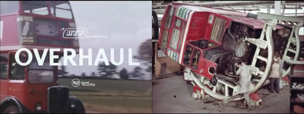
The overhaul works at Aldenham was the subject of a 1957 British Transport Films picture, Overhaul, in which we follow a bus in its journey through the system from tired-out to brand-new. We see the bus given a thorough inspection before being stripped of its upholstery and then having its body separated from its chassis and cleaned, then we see each part being refurbished. Along the way we gain a fascinating insight into the construction of a mid-century passenger transport vehicle, with its wooden frame and aluminium exterior panels being refurbished and rebuilt where necessary, before the camera. Meanwhile we see the chassis, with its separate gearbox in the centre of the vehicle, before it is painted to resist more years of road grime and reunited with a bus body. The completed vehicle is then taken for a test run before being sent to the paint shop for a coat of that iconic London Transport red. Enjoy the film in its entirety below the break.
The buses in the film are the AEC/London Transport “RT” vehicles, which entered service in the late 1930s and last ran in the 1970s. Their replacement, the visually similar “Routemaster” had only started to appear the previous year, and continued in regular service until 2005. Meanwhile the Aldenham bus overhaul works survived until its closure in 1986 due to the appearance of a range of new buses in the capital that did not conform to the standard design that it had been designed to serve.