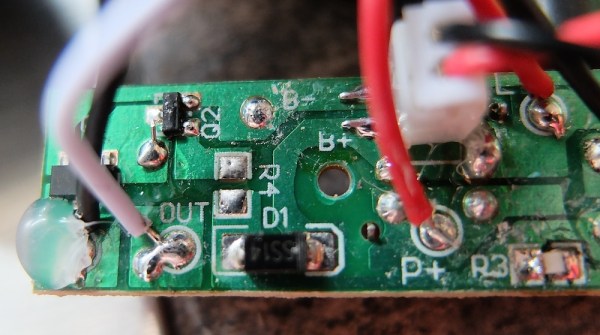
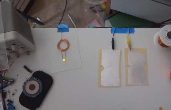
The brain is the most powerful – and least understood computer known to man. For these very reasons, working with the mind has long been an attraction for hackers, makers, and engineers. Everything from EEG to magnetic stimulus to actual implants have found their way into projects. This week’s Hacklet is about some of the best brain hacks on Hackaday.io!
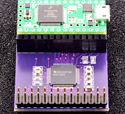 [Paul Stoffregen], father of the Teensy, is hard at work on Biopotential Signal Library, his entry in the 2015 Hackaday Prize. [Paul] isn’t just hacking his own mind, he’s creating a library and reference design using the Teensy 3.1. This library will allow anyone to read electroencephalogram (EEG) signals without having to worry about line noise filtering, signal processing, and all the other details that make recording EEG signals hard. [Paul] is making this happen by having the Teensy’s cortex M4 processor perform interrupt driven acquisition and filtering in the background. This leaves the user’s Arduino sketch free to actually work with the data, rather than acquiring it. The initial hardware design will collect data from TI ADS129x chips, which are 24 bit ADCs with 4 or 8 simultaneous channels. [Paul] plans to add more chips to the library in the future.
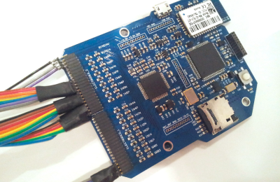 Next up is [Jae Choi] with Lucid Dream Communication Link. [Jae] hopes to create a link between the dream world and the real world. To do this, they are utilizing BioEXG, a device [Jae] designed to collect several types of biological signals. Data enters the system through several active probes. These probes use common pogo pins to make contact with the wearer’s skin. [Jae] says the active probes were able to read EEG signals even through their thick hair! Communication between dreams and the real world will be accomplished with eye movements. We haven’t heard from [Jae] in awhile – so we hope they aren’t caught in limbo!
 [Qquuiinn] is working from a different angle to build bioloop, their entry in the 2015 Hackaday Prize. Rather than using EEG signals, [Qquuiinn] is going with Galvanic Skin Response (GSR). GSR is easy to measure compared to EEG signals. [Qquuiinn] is using an Arduino Pro Mini to perform all their signal acquisition and processing. This biofeedback signal has been used for decades by devices like polygraph “lie detector” machines. GSR values change as the sweat glands become active. It provides a window into a person’s psychological or physiological stress levels. [Qquuiinn] hopes bioloop will be useful both to individuals and to mental health professionals.
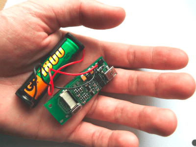 Finally we have [Marcin Byczuk] with Biomonitor. Biomonitor can read both EEG and electrocardiogram (EKG) signals. Unlike the other projects on today’s Hacklet, Biomonitor is wireless. It uses a Bluetooth radio to transmit data to a nearby PC or smartphone. The main processor in Biomonitor is an 8 bit ATmega8L. Since the 8L isn’t up to a lot of signal processing, [Marcin] does much of his filtering the old fashioned way – in hardware. Carefully designed op-amp based active filters provide more than enough performance when measuring these types of signals. Biomonitor has already found it’s way into academia, being used in both the PalCom project, and brain-computer interface research.
If you want more brain hacking goodness, check out our brain hacking project list! Did I miss your project? Don’t be shy, just drop me a message on Hackaday.io. That’s it for this week’s Hacklet, As always, see you next week. Same hack time, same hack channel, bringing you the best of Hackaday.io!

