[FlorianH] has all kinds of new features to show off with this generation of his quadcopter project. Just about everything has seen an upgrade or some other kind of tweak since we looked in on the last version of the aircraft.
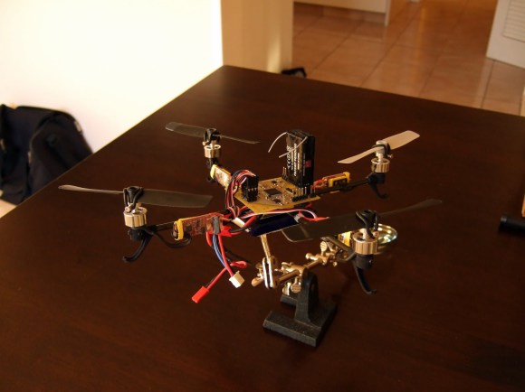
You’ll find some outdoor flight demo clips after the break. Right off the bat we’re impressed at the rock solid stability of the quadrotor while in flight. Even indoors the last version had a hint of a wobble as the control loop calculated stabilization. Here he borrowed some code from the open source Aeroquad project which helps account for this improvement. But the hardware choices lend a hand too. He moved from an ATmega32 up to an STM32F405RG processor. That’s an ARM chip which he programs using one of STM’s Discovery boards. The motors have all been upgraded as well (if you listen in the demo videos for both models you can hear a difference) and he redesigned the frame, which combines carbon tube with 3D printed parts to keep it light yet strong. The upgrade is every bit as impressive as the original build!
Continue reading “[FlorianH] Shows Off MinimaBL, The Next Generation Of His Quadcopter Project”