There’s no doubt that you’ll instantly recognize clips from the video below, as they’ve been used over and over for more than 100 years to illustrate the development of the assembly line. But those brief clips never told the whole story about just how much effort Ford was forced to put into manufacturing just one component of their iconic Model T: the wheels.
An in-house production of Ford Motors, this film isn’t dated, at least not obviously. And with the production of Model T cars using wooden spoked artillery-style wheels stretching from 1908 to 1925, it’s not easy to guess when the film was made. But judging by the clothing styles of the many hundreds of men and boys working in the River Rouge wheel shop, we’d venture a guess at 1920 or so.
Production of the wooden wheels began with turning club-shaped spokes from wooden blanks — ash, at a guess — and drying them in a kiln for more than three weeks. While they’re cooking, a different line steam-bends hickory into two semicircular felloes that will form the wheel’s rim. The number of different steps needed to shape the fourteen pieces of wood needed for each wheel is astonishing. Aside from the initial shaping, the spokes need to be mitered on the hub end to fit snugly together and have a tenon machined on the rim end. The felloes undergo multiple steps of drilling, trimming, and chamfering before they’re ready to receive the spokes.
The first steel component is a tire, which rolls down out of a furnace that heats and expands it before the wooden wheel is pressed into it. More holes are drilled and more steel is added; plates to reinforce the hub, nuts and bolts to hold everything together, and brake drums for the rear wheels. The hubs also had bearing races built right into them, which were filled with steel balls right on the line. How these unsealed bearings were protected during later sanding and grinding operations, not to mention the final painting step, which required a bath in asphalt paint and spinning the wheel to fling off the excess, is a mystery.
Welded steel spoked wheels replaced their wooden counterparts in the last two model years for the T, even though other car manufacturers had already started using more easily mass-produced stamped steel disc wheels in the mid-1920s. Given the massive infrastructure that the world’s largest car manufacturer at the time devoted to spoked wheel production, it’s easy to see why. But Ford eventually saw the light and moved away from spoked wheels for most cars. We can’t help but wonder what became of the army of workers, but it probably wasn’t good. So turn the wheels of progress.
Continue reading “Retrotechtacular: Ford Model T Wheels, Start To Finish” →

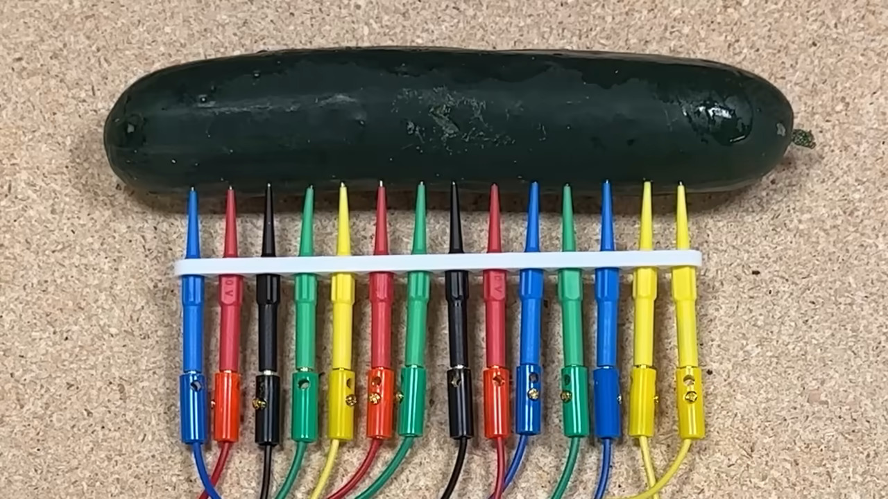 From there, it was a matter of hunting around for spots that produced different notes that sounded good, and marking them for later so it can be played like a potentiometer. But there were problems with this setup, mostly screeching between notes from stray voltages in the environment.