The idea of staggered (or brick) layers in FDM prints has become very popular the past few years, with now nightly builds of OrcaSlicer featuring the ‘Stagger Perimeters’ option to automate the process, as demonstrated by [Stefan] in a recent CNC Kitchen video. See the relevant OrcaSlicer GitHub thread for the exact details, and to obtain a build with this feature. After installing, slice the model as normal, after enabling this new parameter in the ‘Strength’ tab.
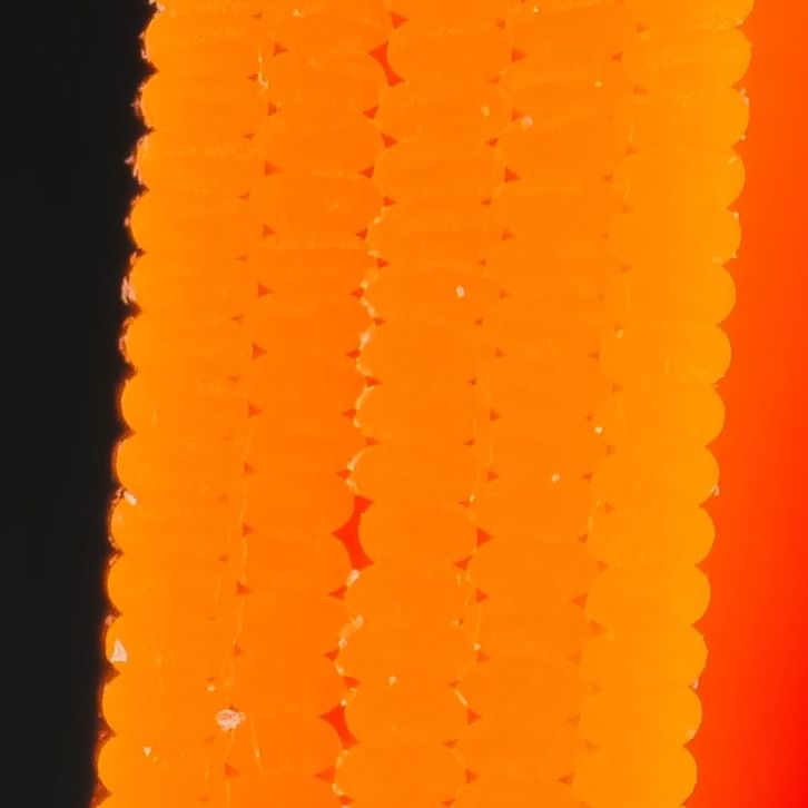
In the video, [Stefan] first tries out a regular and staggered perimeter print without further adjustments. This perhaps surprisingly results in the staggered version breaking before the regular print, which [Stefan] deduces to be the result of increasing voids within the print. After increasing the extrusion rate to 110% to fill up said voids, this does indeed result in the staggered part showing a massive boost in strength.
What’s perhaps more telling is that a similar positive effect is observed when the flow is increased with the non-staggered part, albeit with the staggered part still showing more of a strength increase. This makes it obvious that just staggering layers isn’t enough, but that the flowrate and possibly other parameters have to be adjusted as well to fully realize the potential of brick layers. That said, it’s encouraging to see this moving forward despite questionable patent claims.
Continue reading “Testing Brick Layers In OrcaSlicer With Staggered Perimeters”