When you’re a kid, remote control cars are totally awesome. Even if you can’t go anywhere by yourself, it’s much easier to imagine a nice getaway from the daily grind of elementary school if you have some wheels. And yeah, R/C cars are still awesome once you’re an adult, but actual car-driving experience will probably make you yearn for more realism.
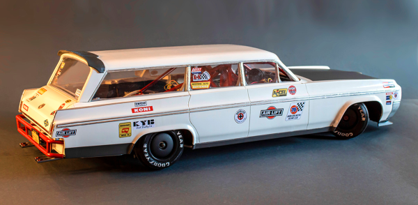
What could be more realistic and fun than an active suspension? Plenty of adults will never get the chance to hit the switches in real car, but after a year of hard work, [snoopybg] is ready to go front and back, side to side, and even drift in this super scale ’63 Oldsmobile Dynamic 88 wagon. We think you’ll agree that [snoopybg] didn’t miss a detail — this thing makes engine noises, and there are LEDs in the dual exhaust pipes to simulate flames.
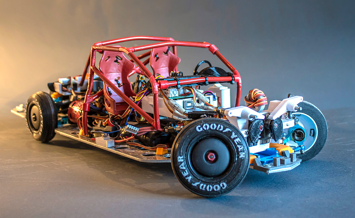 An Arduino reads data from a triple-axis accelerometer in real time, and adjusts a servo on each wheel accordingly, also in real time, to mimic a real car throwing its weight around on a real suspension system. If that weren’t cool enough, most of the car is printed, including the tires. [snoopybg] started with a drift car chassis, but even that has been hacked and drilled out as needed.
There are a ton of nice pictures on [snoopybg]’s site if you want to see what’s under the hood. We don’t see the code anywhere, but [snoopybg] seems quite open to publishing more details if there is interest out there. Strap yourself in and hold on tight, because we’re gonna take this baby for a spin after the break.
If this is all seems a bit much for you, but you’ve got that R/C itch again, there’s a lot to be said for upgrading the electronics in a stock R/C car.