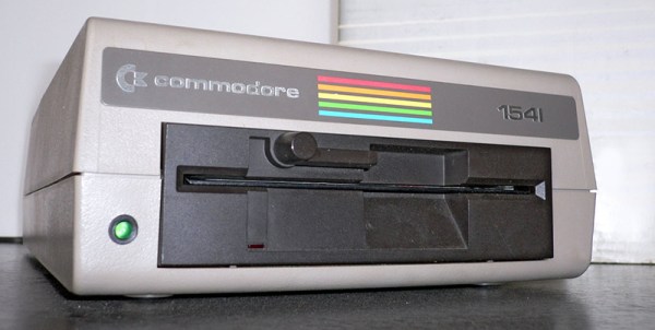
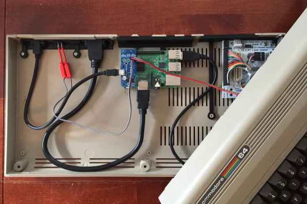
Yellowing: The Plastic Equivalent Of A Sunburn

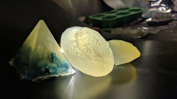
Your fancy white electronic brick of consumer electronics started off white, but after some time it yellowed and became brittle. This shouldn’t have happened; plastic is supposed to last forever. It turns out that plastic enclosures are vulnerable to the same things as skin, and the effects are similar. When they are stared at by the sun, the damage is done even though it might not be visible to you for quite some time.

Continue reading “Yellowing: The Plastic Equivalent Of A Sunburn”

ESP8266 As A Tape Drive

1976 was the year the Apple I was released, one of several computers based on the MOS 6502 chip. MOS itself released the KIM-1 (Keyboard Input Monitor) initially to demonstrate the power of the chip. The single board computer had two connectors on it, one of which could be used for a tape recorder for long-term storage. When [Willem Aandewiel] went to the Apple Museum Nederland in 2016, he saw one and felt nostalgic for his youth. He was able to get a replica, the microKIM, and build it but he wanted to use new technology to interface with this old technology, so he decided to use an ESP8266 as a solid state tape recorder.

One of the reasons the KIM-1 was so popular when it was released was that there was lots of documentation available. [Willem] used this documentation to figure out how the KIM-1 saves data to the recording device. An ATTiny85 is used to decode the pulse stream that the KIM-1 sends when saving because the timing was too tight to both “listen” and decode the bits as well as convert and store them. For loading programs, the data can be sent digitally as 1’s and 0’s to the KIM-1. This means that the ATTiny is only used for decoding and doesn’t have to re-encode the data.  Because of this, saving is slow, but loading is very quick.

To complete the project, [Willem] added four buttons, one each for rewind, record, play and fast-forward, and a screen so you can see which program is currently selected and can go from one program to another. As a nice throwback touch, record and play have to be pressed at the same time when saving. For more 6502 projects, check out this 6502 based DIY computer, or this 6502 built from discrete parts.

Continue reading “ESP8266 As A Tape Drive”

Finally – A Big-Screen Vectrex

The Vectrex is in no way the most popular console of all time, but it is one of the more unique. Eschewing typical raster-based rendering, it instead relies on a vector-based display. Since the average home television of the era would be completely unable to display such signals, the Vectrex had its screen built in. This got [Arcade Jason] wondering – would it be possible to hook the Vectrex up to a bigger screen?

First, a suitable monitor had to be found. The 19V2000 turned out to be a good candidate – much larger at 19 inches, and found in a variety of arcade cabinets from years past. From there, the project became a matter of identifying the signal outputs of the Vectrex. [Arcade Jason] took the liberty of modifying the levels of the signals on the Vectrex board itself, and then fixing the now-overscanned image on the original screen by adjusting the onboard trimpots. With the Vectrex’s X and Y signals now boosted somewhat, they were wired up to the inputs of the larger arcade screen. For the Z signal, things got even hackier – a Walmart “Computer Amplifier”, typically used for speakers, was instead pressed in to service to amplify the signal.

There are plenty of wires running all over the carpet in this video, but the fact is, it works brilliantly. Future plans involve upgrading to an even larger 23 inch monitor, and possibly even experiments with color vector displays. It just goes to show that the Vectrex, even today, maintains a die-hard following.

Perhaps you’d like to try this, but need to fix your original Vectrex screen first? Never fear – that’s possible, too.


Teardown With A Twist: 1975 Sinclair Scientific Calculator

When writing a recent piece about Reverse Polish Notation, or RPN, as a hook for my writing I retrieved my Sinclair Scientific calculator from storage. This was an important model in the genesis of the scientific calculator, not for being either a trailblazer or even for being especially good, but for the interesting manner of its operation and that it was one of the first scientific calculators at an affordable price.

I bought the calculator in a 1980s rummage sale, bodged its broken battery clip to bring it to life, and had it on my bench for a few years. Even in the early 1990s (and even if you didn’t use it), having a retro calculator on your bench gave you a bit of street cred. But then as life moved around me it went into that storage box, and until the RPN article that’s where it stayed. Finding it was a significant task, to locate something about the size of a candy bar in the storage box it had inhabited for two decades, among a slightly chaotic brace of shelves full of similar boxes.

The Sinclair's clean design still looks good four decades later.
The Sinclair’s clean design still looks good four decades later.

Looking at it though as an adult, it becomes obvious that this is an interesting machine in its own right, and one that deserves a closer examination. What follows will not be the only teardown of a Sinclair Scientific on the web, after all nobody could match [Ken Shirriff]’s examination of the internals of its chip, but it should provide an insight into the calculator’s construction, and plenty of satisfying pictures for lovers of 1970s consumer electronics.

The Sinclair is protected by a rigid black plastic case, meaning that it has survived the decades well. On the inside of the case is a crib sheet for its RPN syntax and scientific functions, an invaluable aid when it comes to performing any calculations.

It shares the same external design as the earlier Sinclair Cambridge, a more humble arithmetic calculator, but where the Cambridge’s plastic is black, on the Scientific it is white. The LED display sits behind a purple-tinted window, and the blue-and-black keyboard occupies the lower two-thirds of the front panel. At 50 x 111 x 16 mm it is a true pocket calculator, with an elegance many of its contemporaries failed to achieve and which is certainly not matched by most recent calculators. Good industrial design does not age, and while the Sinclair’s design makes it visibly a product of the early 1970s space-age aesthetic it is nevertheless an attractive item in its own right.

Continue reading “Teardown With A Twist: 1975 Sinclair Scientific Calculator”

An Amstrad PCW For The 21st Century

If you were a computer-mad teen in the late 1980s, you were probably in the process of graduating from an 8-bit machine to a 16-bit one, maybe an Amiga, or an Atari ST. For the first time though you might not have been the only computer owner in your house, because there was every chance your parents might have joined the fun with a word processor. Maybe American home offices during this period might have had PC clones, but for Brits there was every chance that the parental powerhouse would have been an Amstrad PCW.

Amstrad were the masters of packaging up slightly outdated technology for electronic consumers on a budget, and the PCW was thus a 1970s CP/M machine for the 1980s whose main attraction was that it came with monitor and printer included in the price. [James Ots]’ parents had one that interested him enough that  he has returned to the platform and is documenting his work bringing it up to date.

It was the most recent progress in booting into CP/M from an SD card by hijacking the printer ROM that caught our eye, but reading all the build logs that is only the tip of the iceberg. He’s connected another monitor, made a joystick port and a soundcard, and added a memory upgrade to his PCW. Most of these machines would have only been used with the bundled word processor, so those are real enhancements.

We’ve featured quite a few projects involving Amstrad’s CPC home computers, such as this one with a floppy emulator. Amstrad are an interesting company for followers of consumer electronics of the ’70s and ’80s, they never had the out-there tech wackiness of their great rival Sinclair but their logo could be found on an astonishing variety of appliances. The “AMS” in Amstrad are the initials of the company founder [Alan Sugar], who is rather better known in 2017 as the British host of The Apprentice. It is not known whether he intends to lead the country.

PCB Tesla Coil Is Perfect Desk Toy

A Tesla coil easily makes it to the top spot on our list of “Mad Scientist” equipment we want for the lab, second only to maybe a Jacob’s Ladder. Even then, it’s kind of unfair advantage because you know people only want a Jacob’s Ladder for that awesome sound it makes. Sound effects not withstanding, it’s Tesla coil all the way, no question.

Unfortunately, winding your own Tesla coil is kind of a hassle. Even on relatively small builds, you’ll generally need to setup some kind of winding jig just to do the secondary coil, which can be a project in itself. So when [Daniel Eindhoven] sent his no-wind Tesla coil into the tip line, it immediately got our attention.

The genius in his design is that the coils are actually etched into the PCB, completely taking the human effort out of the equation. Made up of 6 mil traces with 6 mil separation, the PCB coil manages to pack a 25 meter long, 160 turn coil into an incredibly compact package. As you might expect, such a tiny Tesla coil isn’t exactly going to be a powerhouse, and in fact [Daniel] has managed to get the entirely thing running on the 500 mA output of your standard USB 2.0 port.

In such a low-power setup, [Daniel] was also able to replace the traditional spark gap pulse generator with a PIC18F14K50 microcontroller, further simplifying the design. An advantage of using a microcontroller for the pulse generator is that it’s very easy to adjust the coil’s operating frequency, allowing for neat tricks like making the coil “sing” by bringing its frequency into the audible range.

For those looking to build their own version, [Daniel] has put the PCB schematic and firmware available for download on his site. He also mentions that, in collaboration with Elektor magazine, he will be producing a kit in the near future. Definitely something we’ll be keeping an eye out for.

Incidentally, this isn’t the first time [Daniel] has demonstrated his mastery of high voltage. He scared impressed us all the way back in 2010 with his 11,344 Joule capacitor bank, perfect for that laptop-destroying rail gun you’ve been meaning to build.

Continue reading “PCB Tesla Coil Is Perfect Desk Toy”

Analyzing The 6502 With Python And Cheap Dev Boards

The Before Times were full of fancy logic analyzers. Connect the leads on these analyzers to a system, find that super special ROM cartridge, and you could look at the bus of a computer system in real time. We’ve come a long way since then. Now we have fast, cheap bits of hardware that can look at multiple inputs simultaneously, and there are Open Source solutions for displaying and interpreting the ones and zeros on a data bus. [hoglet] has built a very clever 6502 protocol decoder using Sigrok and a cheap 16-channel logic analyzer.

This protocol decoder is capable of looking at the ones and zeros on the data bus of a 6502-based computer. Right now, [hoglet] able to stream two million 6502 cycles directly to memory, so he’s able to capture the entire startup sequence of a BBC Micro. The hardware for this build was at first an Open Bench Logic Sniffer on a Papilio One FPGA board. This hardware was changed to an impressively inexpensive Cypress FX2 development board that was reconfigured to a 16 channel logic analyzer.

The software stack is where this really shines, and here [hoglet] documented most of the build over on the stardot forums. The basic capture is done with Sigrok, the Open Source signal analysis toolchain. This project goes a bit further than simply logging ones and zeros to a file. [hoglet] designed an entire 6502 protocol decoder with Python. Here’s something fantastic: this was [hoglet]’s first major Python project.

To capture the ones and zeros coming out of a 6502, the only connections are the eight pins on the data bus, RnW, Sync, Rdy, and Phy2. That’s only twelve pins, and no connections to the address bus, but the protocol decoder quickly starts to predict what the current program counter should be. This is a really fantastic piece of work, enabling an entire stack trace on any 6502 computer for less than $20 in parts.