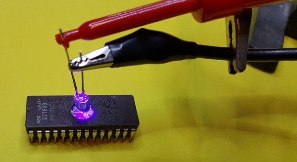
We’re all too spoiled nowadays with our comfortable ways to erase and write data to persistent memory, whether it’s our microcontroller’s internal flash or some external EEPROM. Admittedly, those memory technologies aren’t exactly new, but they stem from a time when their predecessors had to bathe under ultraviolet light in order to make space for something new. [Taylor Schweizer] recently came across some of these quartz-window decorated chips, and was curious to find out what is stored in them. Inspired by the BIOS reverse engineering scene in Halt and Catch Fire, he ended up building his own simple reader to display the EPROM’s content.
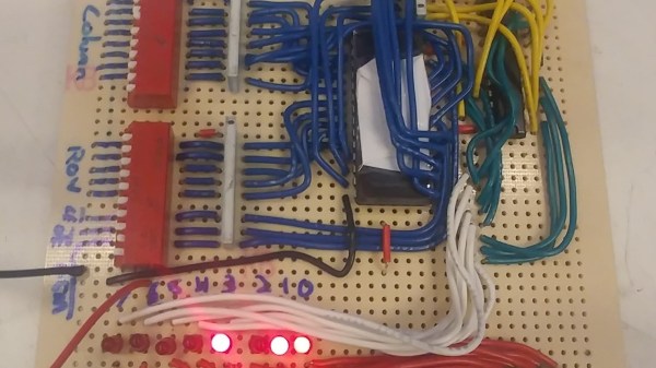
The 2732 he uses is a standard EPROM with 32kbit memory. Two pins, Chip Enable and Output Enable, serve as main control interface, while 12 address pins select the data stored in the chip’s internal 4K x 8 arrangement, to output it on the 8 data output pins. You could of course hook up the EPROM to a microcontroller and send what you read via serial line, but [Taylor] opted for a more hands-on approach that lets him read out the data in a manual way. He simply uses a bank of DIP switches to set the address and control pins, and added a row of LEDs as display.
As you can see from the short demonstration in the video after the break, reading out the entire EPROM would be a rather tedious task this way. If you do have more serious intentions to read out the content, you could have a look at one of those microcontroller based solutions sending data via serial line after all.