[Bren Sutton] has been a long time fan of SEGA’s Dreamcast, eagerly snapping one up right around its October 1999 European release. But after years of neglect and a somewhat questionable paint job a decade or so back, he decided it was time to spruce his old friend up. He could have just cleaned the machine and been done with it, but he took the opportunity to revamp the console’s internals with both practical and cosmetic trickery.
The first step was getting the system looking a bit fresher. Removing the silver metallic paint he applied in his youth with a rattle can wasn’t going so well, so he ended up buying a broken donor console on eBay so he’d have a new shell to work with. The donor was yellowed with age, but a coating of peroxide cream and a few hours under a cheap UV light got it whitened up nicely. Now that he had a fresh new case, [Bren] turned his attention to the internal components.
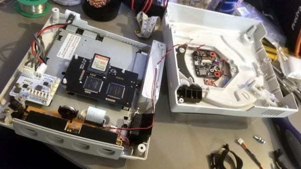
 Those who might be plugged into the active Dreamcast homebrew scene may already know that several upgrade modules exist for SEGA’s last home game console. One of the most popular replaces the optical drive with an SD card filled with your favorite game ISOs. You can also get a modern high efficiency power supply, as well as a board that replaces the original soldered-on clock battery with a slot that fits a CR2032. [Bren] threw them all in, ensuring several more years of gaming bliss.
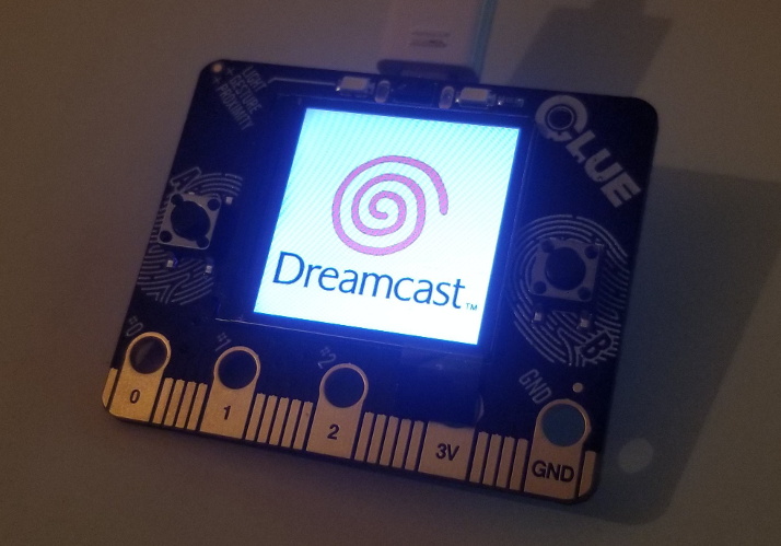
But he wasn’t done yet. He also wanted to add some visual flair to his new and improved console. After some consideration, he gingerly cut the logo out of the Dreamcast’s lid, and installed an Adafruit CLUE board underneath it. With a few carefully crafted GIFs installed onto the CircuitPython-powered board, the console now has a gorgeous fully animated logo that you can see in the video after the break.
[Bren] could have really taken his console to the next level by doubling its available RAM to an eye-watering 32 MB, but considering the limited software support for that particularly bodacious modification, we’ll let it slide. Continue reading “Restored Dreamcast Is A SEGA Fan’s Dream Come True”