Word clocks are one of those projects that everyone seems to love. Even if you aren’t into the tech behind how they work, they have a certain appealing aesthetic. Plus you can read the time without worrying about those pesky numbers, to say nothing of those weird little hands that spin around in a circle. This is the 21st century, who has time for that?
 Now, thanks to [Gordon Williams], these decidedly modern timepieces just got a lot more accessible. His word clock is not only small enough to fit in the palm of your hand, but it’s the easiest-to-build one we’ve ever seen. If you were ever curious about these gadgets but didn’t want to put in the the time and effort required to build a full scale version, this diminutive take on the idea might be just what Father Time ordered.
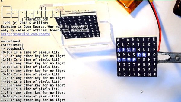
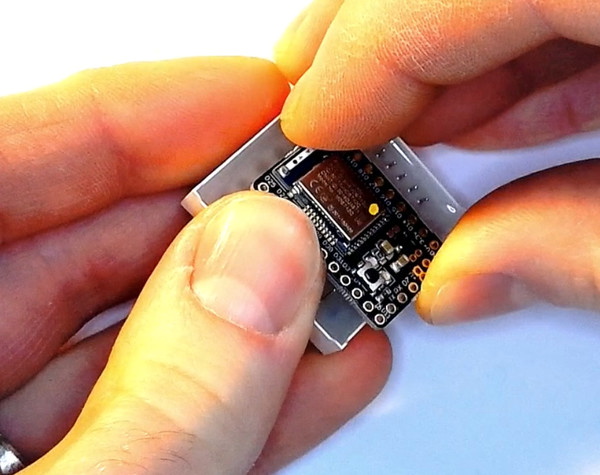
The trick is to attach the microcontroller directly to the backside of an 8 x 8 LED matrix. As demonstrated by [Gordon], the Bluetooth-enabled Espruino MDBT42Q fits neatly between the rows of pins, which need only a gentlest of persuasions to get lined up and soldered into place. Since the time can be set remotely over Bluetooth, there’s not even so much as an additional button required. While driving the LEDs directly off of the digital pins of a microcontroller is never recommended, the specifics of this application (only a few of the LEDs on at a time, and not for very long) means he can get away with it.
Of course, that just gets you an array of square LEDs you blink. It wouldn’t be much of a word clock without, you know, words. To that end, [Gordon] has provided an overlay which you can print on a standard inkjet printer. While it’s not a perfect effect as the light still comes through the ink, it works well enough to get the point across. One could even argue that the white letters on the gray background helps with visibility compared to just the letters alone lighting up.
If you’re not in the market for a dollhouse-sized word clock, fear not. We’ve got no shortage of adult sized versions of these popular timepieces for your viewing pleasure.