In case you haven’t heard, the best hardware conference in the world was last weekend. The Hackaday Superconference was three days of hardware hacking, soldering irons, and an epic hardware badge. Throw in two stages for talk, two workshop areas, the amazing hallwaycon and the best, most chill attendees you can imagine, and you have the ultimate hardware conference.
Already we’ve gone over the gory details of what this badge does, and now it’s time to talk about the perils of building large numbers of an electronic conference badge. This is the hardware demoscene, artisanal manufacturing, badgelife, and an exploration of exactly how far you can push a development schedule to get these badges out the door and into the hands of eager badge hackers and con attendees.
The good news is that we succeeded, and did so in time to put a completed badge in the hand of everyone who attended the conference (and we do have a few available if you didn’t make it to the con). Join me after the break to learn what it took to make it all happen and see the time lapse of the final kitting process.
We live in an electromagnetic soup, bombarded by wavelengths from DC to daylight and beyond. A lot of it is of our own making, especially further up the spectrum where wavelengths are short enough for the bandwidth needed for things like WiFi and cell phones. But long before humans figured out how to make their own electromagnetic ripples, the Earth was singing songs at the low end of the spectrum. The very low frequency (VLF) band abounds with interesting natural emissions, and listening to these Earth sounds can be quite a treat.
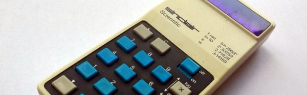
When writing a recent piece about Reverse Polish Notation, or RPN, as a hook for my writing I retrieved my Sinclair Scientific calculator from storage. This was an important model in the genesis of the scientific calculator, not for being either a trailblazer or even for being especially good, but for the interesting manner of its operation and that it was one of the first scientific calculators at an affordable price.
I bought the calculator in a 1980s rummage sale, bodged its broken battery clip to bring it to life, and had it on my bench for a few years. Even in the early 1990s (and even if you didn’t use it), having a retro calculator on your bench gave you a bit of street cred. But then as life moved around me it went into that storage box, and until the RPN article that’s where it stayed. Finding it was a significant task, to locate something about the size of a candy bar in the storage box it had inhabited for two decades, among a slightly chaotic brace of shelves full of similar boxes.
The Sinclair’s clean design still looks good four decades later.
Looking at it though as an adult, it becomes obvious that this is an interesting machine in its own right, and one that deserves a closer examination. What follows will not be the only teardown of a Sinclair Scientific on the web, after all nobody could match [Ken Shirriff]’s examination of the internals of its chip, but it should provide an insight into the calculator’s construction, and plenty of satisfying pictures for lovers of 1970s consumer electronics.
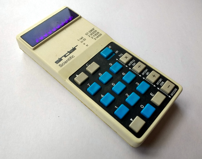
The Sinclair is protected by a rigid black plastic case, meaning that it has survived the decades well. On the inside of the case is a crib sheet for its RPN syntax and scientific functions, an invaluable aid when it comes to performing any calculations.
It shares the same external design as the earlier Sinclair Cambridge, a more humble arithmetic calculator, but where the Cambridge’s plastic is black, on the Scientific it is white. The LED display sits behind a purple-tinted window, and the blue-and-black keyboard occupies the lower two-thirds of the front panel. At 50 x 111 x 16 mm it is a true pocket calculator, with an elegance many of its contemporaries failed to achieve and which is certainly not matched by most recent calculators. Good industrial design does not age, and while the Sinclair’s design makes it visibly a product of the early 1970s space-age aesthetic it is nevertheless an attractive item in its own right.
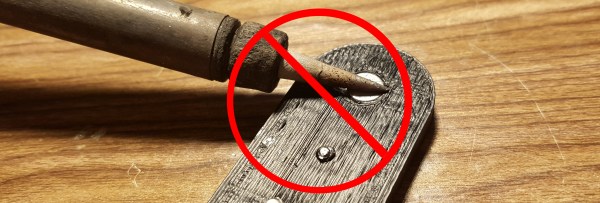
There’s a trick in the world of plastic enclosures. The threaded insert is a small cylinder of metal with threads on the inside and a rough edge on the outside. To make a plastic part with a hole for securely connecting bolts that can be repeatedly screwed without destroying the plastic, you take the threaded insert and press it (usually with the help of a soldering iron to heat the insert) into a hole that’s slightly smaller than the insert. The heat melts the plastic a little bit and allows for the insert to go inside. Then when it cools the insert is snugly inside the plastic, and you can attach circuit boards or other plastic parts using a bolt without stripping the screw or the insert. We’ve seen Hackaday’s [Joshua Vasquez] installing threaded inserts with an iron, as well as in a few other projects.
This trick is neat. And I’ve now proven that it does not work with neodymium magnets.
They say that a picture is worth a thousand words. But what is a picture exactly? One definition would be a perfect reflection of what we see, like one taken with a basic camera. Our view of the natural world is constrained to a bandwidth of 400 to 700 nanometers within the electromagnetic spectrum, so our cameras produce images within this same bandwidth.
For example, if I take a picture of a yellow flower with my phone, the image will look just about how I saw it with my own eyes. But what if we could see the flower from a different part of the electromagnetic spectrum? What if we could see less than 400 nm or greater than 700 nm? A bee, like many other insects, can see in the ultraviolet part of the spectrum which occupies the area below 400 nm. This “yellow” flower looks drastically different to us versus a bee.
In this article, we’re going to explore how images can be produced to show spectral information outside of our limited visual capacity, and take a look at the multi-spectral cameras used to make them. We’ll find that while it may be true that an image is worth a thousand words, it is also true that an image taken with a hyperspectral camera can be worth hundreds of thousands, if not millions, of useful data points. Continue reading “Hyperspectral Imaging – Seeing The Unseeable”→
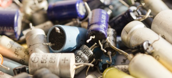
People talk about active and passive components like they are two distinct classes of electronic parts. When sourcing components on a BOM, you have the passives, which are the little things that are cheaper than a dime a dozen, and then the rest that make up the bulk of the cost. Diodes and transistors definitely fall into the cheap little things category, but aren’t necessarily passive components, so what IS the difference?
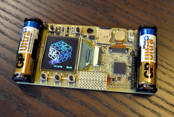
The best hardware conference is just a few weeks away. This is the Hackaday Superconference, and it’s two days of talks, an extra day of festivities, soldering irons, and an epic hardware badge. We’ve been working on this badge for a while now, and it’s finally time to share some early details. This is an awesome badge and a great example of how to manufacture electronics on an extremely compressed timetable. This is badgelife, the hardware demoscene of electronic conference badges.
So, what does this badge do? It’s a camera. It has games, and it’s designed by [Mike Harrison] of Mike’s Electric Stuff. He designed and prototyped this badge in a single weekend. On board is a PIC32 microcontroller, an OV9650 camera module, and a bright, crisp 128×128 resolution color OLED display. Tie everything together with a few buttons, and you have a badge that’s really incredible.
So, how do you get one? You’ve got to come to the Hackaday Superconference. This year we’re doing things a bit differently and opening the doors a day early to get the hacker village started with badge hacking topped off by a party that evening and everyone coming to Supercon is invited! This is a badge full of games, puzzles, and video capture and isn’t something to miss. We have less than 30 tickets left so grab your ticket now and read on.