Summer is the season for family road trips here in the US, and my family took to the open road in a big way this year. We pulled off a cross-country relocation, from Connecticut to Idaho. Five days on the road means a lot of pit stops, and we got to see a lot of truck stops and consequently, a lot of long-haul truckers. I got to thinking about their unique lifestyle and tried to imagine myself doing that job. I wondered what I’d do hour after long hour, alone in the cab of my truck. I figured that I’d probably just end up listening to a lot of audio books, but then I realized that there’s a perfect hobby for the road — ham radio. So I decided to see how ham radio is used by truckers, and mull over how a truck driver version of me might practice The World’s Best Hobby.
Imagine this: you come home after a day at work. As you open the door, your nose is the first alert that something is very, very wrong. Instead of the usual house smell, your nose is assaulted with the distinctive aroma that means your dog had an accident. The smell is stronger though — as if Fido brought over a few friends and they all had a party. Flipping the lights on, the true horror is revealed to you. This was a team effort, but only one dog was involved.
At some point after the dog’s deed, Roomba, your robot vacuum, took off on its scheduled daily run around the house. The plucky little robot performed its assigned duties until it found the mess. The cleaning robot then became an agent of destruction, smearing a foul smelling mess throughout the space it was assigned to clean. Technology sometimes has unintended consequences. This time, your technology has turned against you.
This scene isn’t a work of fiction. For a select few families, it has become an all too odoriferous reality just begging for a clever fix.
When was the last time you went to a library? If it’s been more than a couple of years, the library is probably a very different place than you remember. Public libraries pride themselves on keeping up with changing technology, especially technology that benefits the communities they serve. No matter your age or your interests, libraries are a great resource for learning new skills, doing research, or getting help with just about any task. After all, library science is about gathering together all of human knowledge and indexing it for easy lookup.
It doesn’t matter if you’re not a researcher or a student. Libraries exist to serve everyone in a class-free environment. In recent years, patrons have started looking to libraries to get their piece of the burgeoning DIY culture. They want to learn to make their lives better. Public libraries have stepped up to meet this need by adding new materials to their collections, building makerspaces, and starting tool libraries. And this is in addition to ever-growing collections of electronic resources. Somehow, they manage to do all of this with increasingly strained budgets.
The purpose of this article is to explore the ways that libraries of all stripes can be a valuable resource to our readers. From the public library system to the sprawling academic libraries on college campuses, there is something for hackers and makers at all levels.
I learned some basic electronics in high school physics class: resistors, capacitors, Kirchhoff’s law and such, and added only what was required for projects as I did them. Then around 15 years ago I decided to read some books to flesh out what I knew and add to my body of knowledge. It turned out to be hard to find good ones.
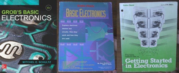
The electronics section of my bookcase has a number of what I’d consider duds, but also some gems. Here are the gems. They may not be the electronics-Rosetta-Stone for every hacker, but they are the rock on which I built my church and well worth a spot in your own reading list.
Grob’s Basic Electronics
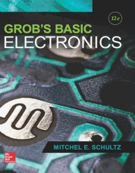
Grob’s Basic Electronics 12th Edition
Grob’s Basic Electronics by Mitchel E Schultz and Bernard Grob is a textbook, one that is easy to read yet very thorough. I bought mine from a used books store. The 1st Edition was published in 1959 and it’s currently on the 12th edition, published in 2015. Clearly this one has staying power.
I refer back to it frequently, most often to the chapters on resonance, induction and capacitance when working on LC circuits, like the ones in my crystal radios. There are also things in here that I couldn’t find anywhere else, including thoroughly exhaustive online searches. One such example is the correct definitions and formulas for the various magnetic units: ampere turns, field intensity, flux density…
I’d recommend it to a high school student or any adult who’s serious about knowing electronics well. I’d also recommend it to anyone who wants to reduce frustration when designing or debugging circuits.
Series-Resonance calculations
Series-Resonance schematic
You can find the table of contents here but briefly it has all the necessary introductory material on Ohm’s and Kirchhoff’s laws, parallel and series circuits, and so on but to give you an idea of how deep it goes it also has chapters on network theorems and complex numbers for AC circuits. Interestingly my 1977 4th edition has a chapter on vacuum tubes that’s gone in the current version and in its place is a plethora of new ones devoted to diodes, BJTs, FETs, thyristors and op-amps.
You can also do the practice problems and self-examination, just to make sure you understood it correctly. (I sometimes do them!) But also, being a textbook, the newest edition is expensive. However, a search for older but still recent editions on Amazon turns up some affordable used copies. Most of basic electronics hasn’t changed and my ancient edition is one of my more frequent go-to books. But it’s not the only gem I’ve found. Below are a few more.
Even in this age of wearable technology, the actual fabric in our t-shirts and clothes may still be the most high-tech product we wear. From the genetically engineered cotton seed, though an autonomous machine world, this product is manufactured in one of the world’s largest automation bubbles. Self-driving cotton pickers harvest and preprocess the cotton. More machines blend the raw material, comb it, twist and spin it into yarn, and finally, a weaving machine outputs sheets of spotless cotton jersey. The degree of automation could not be higher. Except for the laboratories, where seeds, cotton fibers, and yarns are tested to meet tight specifications, woven fabrics originate from a mostly human-free zone that is governed by technology and economics.
Measuring length is a pain, and it’s all the fault of Imperial measurements. Certain industries have standardized around either Imperial or metric, which means that working on projects across multiple industries generally leads to at least one conversion. For everyone outside the last bastion of Imperial units, here’s a primer on how we do it in crazy-land.
Definitions
The basic unit of length measurement in Imperial units is the inch. twelve inches make up one foot, three feet make up one yard, and 5,280 feet (or 1,760 yards) make up a mile. Easy to remember, right?
Ironically, an inch is defined in metric as 25.4 millimeters. You can do the rest of the math for exact lengths, but in general, three feet is just shy of a meter, and a mile is about a kilometer and a half. Generally in Imperial you’ll see lots of mixed units, like a person’s height is 6’2″ (that’s shorthand for six feet, two inches.) But it’s not consistent, it’s English; the only consistency is that it’s always breaking its own rules. You wouldn’t say three yards, two feet, and six inches; you’d say 11 1/2 feet. If it was three yards, one foot, and six inches, though, you’d say 3 1/2 yards. There’s no good rule for this other than try to use nice fractions as often as you can.
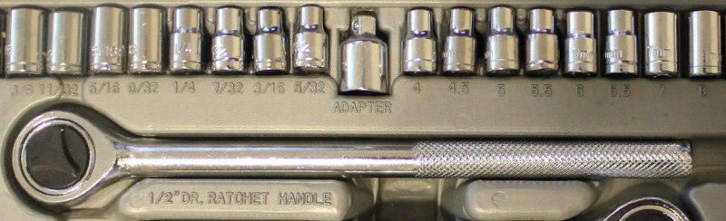
Users of Imperial units love fractions, especially when it comes to parts of an inch or mile. You’ll frequently find drill bits in fractions of an inch, which can be extremely frustrating when you are trying to do math in your head and figure out if a 17/64″ bit is bigger than a 1/4″ bit (hint, yes, it’s 1/64″ bigger).
A socket wrench set in Imperial fractions on the left and metric on the right. Metric is so much easier.
If it wasn’t hard enough already, there came the thousandth of an inch. As the machine age was getting better and better, and parts were getting smaller and more precise, there came a need for more accurate measurements than 1/64 inch. Development of appropriate tools for measuring such fine resolution was critical as well. You can call a 1/8″ bit a .125″ bit, and that means 125 thousandths of an inch. People didn’t like to wrap their mouths around that whole word, though, so it was reduced to “thou.” Others used the latin root for thousand, “mil.” To summarize, a mil is the equivalent of a thou, which is one thousandth of an inch. It should not be confused with a millimeter. It takes about 40 mils to make 1 millimeter. Also, the plural of mil is mils, and the plural of thou is thou.
Tools
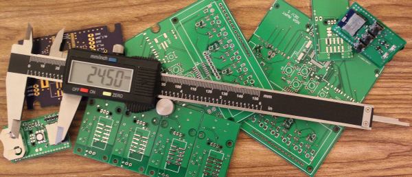
Outside calipers for measuring the outer dimensionBy Glenn McKechnie (Own work) [GFDL, CC-BY-SA-3.0 or CC BY-SA 2.5-2.0-1.0], via Wikimedia CommonsMeasuring length is done with a variety of tools, from GPS for long distances, to tape measures for feet/meters, and rulers for inches/centimeters. When it comes to very small measurements, the caliper is the tool of choice. This is the kind of tool that should be in everyone’s toolbox. Initially it started with the inside caliper and outside caliper, which were separate tools used to measure lengths. The Vernier caliper combined the two, added a depth meter and a couple other handy features, and gave machinists an all-around useful tool for measuring. Just like the slide rule, though, as soon as digital options became available, they took over. The digital caliper can usually switch modes between decimal inches, fractional inches, and metric.
Every industry has picked a different convention. Plastic sheets are usually measured in mils for thin stuff and millimeters or fractions of an inch for anything greater than 1/32″. Circuit boards combine units in every way imaginable, sometimes combining mils for trace width and metric for board dimensions, with the thickness of the copper expressed in ounces. (That’s not even a unit of length! It represents the amount of copper in one square foot of area and 1 oz is equivalent to 1.4mil.) Most of the time products designed outside of the U.S. are in metric units, while U.S. products are designed in either. When combining different industries, though, the difference in standards gets really annoying. For example, order 1/8″ plexiglass, and you may get 3mm plexiglass instead. Sure the difference is only .175mm (7 thou), but that difference can cause big problems for pieces that are press fit or when making finger joints on boxes, so it’s important that when sourcing components, you not only verify the unit, but if it’s a normal unit for that industry and it’s not just being rounded.
Often you can tell with what primary unit a product is designed with only a few measurements of a caliper. Find a dimension and see if it’s a nice round number in metric. If it’s not, switch it to imperial, and watch how quickly it snaps to a nice number.
Moving forward
Use metric if you can. The vast majority of the world does it. When you are sending designs overseas for production they will convert to metric (though they are used to working in both). It does take time to get used to it (especially when you are dealing with thou/mils), but your temporary discomfort will turn to relief when your design doesn’t crash into the Mars (or more realistically when you don’t have to pull out the Dremel and blade to get your parts to fit together).
Wood. Humans have burned it for to heat their homes for thousands of years. It’s truly a renewable source of energy. While it may not be the most efficient or green method to warm a space, it definitely gets the job done. Many homes still have a fireplace or wood burning stove for supplemental heat. For those in colder climates, wood is more than just supplemental, it’s needed simply for survival.
Splitting maul by Chmee2 via Wikipedia
The problem with firewood is that it doesn’t come ready to burn. Perfect fireplace sized chunks don’t grow on trees after all. The trees have to be cut up into logs. The logs must be split. The split wood then needs to dry for 6 months or so.
Anyone who’s spent time manually splitting wood can tell you it’s back breaking work. Swinging an 8 pound maul for a few hours will leave your hands numb and your shoulders aching. It’s the kind of work that leaves the mind free to wander a bit. The hacker’s mind will always wander toward a better way to get the job done. Curiously we haven’t seen too many log splitting hacks here on the blog. [KH4] built an incredible cross bladed axe back in 2015, but that’s about it.






![Outside calipers for measuring the outer dimensionBy Glenn McKechnie (Own work) [GFDL, CC-BY-SA-3.0 or CC BY-SA 2.5-2.0-1.0], via Wikimedia Commons](https://hackaday.com/wp-content/uploads/2016/07/outsidecalipers.jpg?w=400)