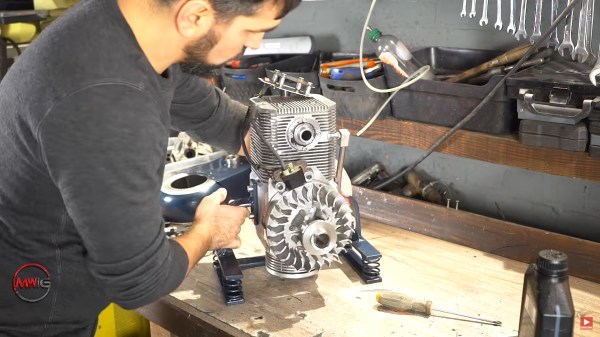
When hackers in the US think of a retailer called Harbor Freight, we usually think of cheap tools, workable but terrible DVM’s, zip ties, and tarps. [Jimbo] over at [Robot Cantina] looked at the 212cc “Predator” engine that they sell and thought “I bet I could power my Honda Insight with that.” And he did, successfully! How much power did the heavily modified engine make? In the video below the break, [Jimbo] takes us through the process of measuring its output using a home built dyno.
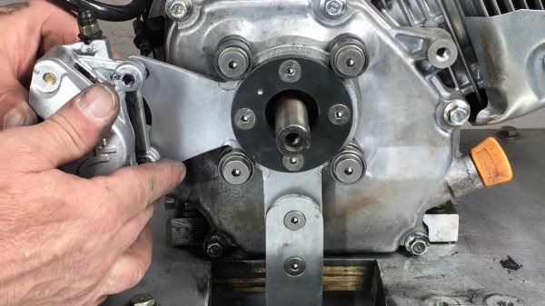
The dyno that [Jimbo] has built is a Prony Dyno, and it’s among the oldest and simplest designs available. A torque arm is extended from a disk brake caliper and connects to a force gauge. The engine is ran up to its highest speed, and then he brake is applied to the crankshaft until the engine almost stalls. A tachometer keep track of the RPM, and the force gauge measures the force on the torque arm. Torque is multiplied by RPM and the result is divided by a constant of 5252, and voilà: Horsepower. A computer plots the results across the entire range, and the dyno test is complete.
That only tells part of the story, and the real hack comes when you realize that the dyno stand, the force gauge setup and pretty much everything that can be built at home has been built at home. You’ll also enjoy seeing the results of some driving tests between the 212cc engine and its bigger 420cc brother, how even minor changes to the engine affect the horsepower and torque curves, and how that affects the Honda that he calls his “Street legal go cart.”
Speaking of unusual power plants, how about plant some hobby sized jet turbines on the back of your Tesla for fun?
Continue reading “DIY Prony Dyno Properly Displays Power Production”