This excellent content from the Hackaday writing crew highlights recurring topics and popular series like Linux-Fu, 3D-Printering, Hackaday Links, This Week in Security, Inputs of Interest, Profiles in Science, Retrotechtacular, Ask Hackaday, Teardowns, Reviews, and many more.
If you measure a DC voltage, and want to get some idea of how “big” it is over time, it’s pretty easy: just take a number of measurements and take the average. If you’re interested in the average power over the same timeframe, it’s likely to be pretty close (though not identical) to the same answer you’d get if you calculated the power using the average voltage instead of calculating instantaneous power and averaging. DC voltages don’t move around that much.
Try the same trick with an AC voltage, and you get zero, or something nearby. Why? With an AC waveform, the positive voltage excursions cancel out the negative ones. You’d get the same result if the flip were switched off. Clearly, a simple average isn’t capturing what we think of as “size” in an AC waveform; we need a new concept of “size”. Enter root-mean-square (RMS) voltage.
To calculate the RMS voltage, you take a number of voltage readings, square them, add them all together, and then divide by the number of entries in the average before taking the square root: . The rationale behind this strange averaging procedure is that the resulting number can be used in calculating average power for AC waveforms through simple multiplication as you would for DC voltages. If that answer isn’t entirely satisfying to you, read on. Hopefully we’ll help it make a little more sense.
This Friday, Hackaday.io will be graced with purveyors of Open Source Silicon. Join us in the Hackaday.io Hack Chat this Friday, April 14 at noon PDT (19:00 UTC) for a conversation with SiFive, an ‘Open’ silicon manufacturer.
This week, we’re sitting down with SiFive, a fabless semiconductor company and makers of the HiFive1, an Open Hardware microcontroller that you can just go out and buy. Late last year, SiFive released the HiFive1, an Arduinofied version of SiFive’s FE310 System on Chip. This SoC is a RISC-V core and one of the first microprocessors that is completely Open Source. It is an affront to Stallmanism, the best hope we have for truly Open hardware, and it’s pretty fast, to boot.
SiFive isn’t only working on Open Hardware microcontrollers — their business plan is pretty much, ‘OSH Park, but for silicon’. If you have a design for a new type of chip, they’ll work with foundries to turn your design into a cute little epoxy impregnated blob. It’s a fascinating business plan, and you’re going to hear all about it this Friday in the Hack Chat.
Here’s How To Take Part:
Our Hack Chats are live community events on the Hackaday.io Hack Chat group messaging.
Log into Hackaday.io, visit that page, and look for the ‘Join this Project’ Button. Once you’re part of the project, the button will change to ‘Team Messaging’, which takes you directly to the Hack Chat.
You don’t have to wait until Friday; join whenever you want and you can see what the community is talking about.
Upcoming Hack Chats
We’ve got a lot on the table when it comes to our Hack Chats. On April 21st, we’re going to be talking magnets with Nanomagnetics. Making magnets, collecting magnets, playing with magnets, it’ll all be over on the Hack Chat.
The hardware coming out of [Dr. Peter Jansen]’s lab is the craziest stuff you can imagine. He’s built a CT scanner out of plywood, and an MRI machine out of many, many turns of enamel wire. Perhaps his best-known build is his Tricorder – a real, all-sensing device with permission from the estate of [Gene Roddenberry] to use the name. [Peter]’s tricorder was one of the finalists for the first Hackaday Prize, but that doesn’t mean he’s stopped working on it. Sensors are always getting better, and by sometime in the 23rd century, he’ll be able to fit a neutrino detector inside a tiny hand-held device.
One of the new sensors [Peter] is working with is the MAX30105 air particle sensor. The marketing materials for this chip say it’s designed for smoke detectors and fire alarms, but this is really one of the smallest dust and particle sensors on the market. If you want a handheld device that detects dust, this should be the chip you’re looking at.
Unfortunately, Maxim is being very, very tight-lipped about how this particle sensor works. There is a way to get access to raw particle counts and the underlying algorithms, and Maxim is more than willing to sell those algorithms through a third-party distributor. That’s simply not how we do things around here, so [Peter] is looking for someone with a fancy particle sensor to collect a few hours of data so he can build a driver for this chip.
Here’s what we know about the MAX30105 air particle sensor. There are three LEDs inside this chip (red, IR, and green), and an optical sensor underneath a piece of glass. The chip drives the LEDs, light reflects off smoke particles, and enters the optical sensor. From there, magic algorithms turn this into a number corresponding to a particle count. [Peter]’s hackaday.io log for this project has tons of data, math, and statistics on the data that comes out of this sensor. He’s also built a test rig to compare this sensor with other particle sensors (the DSM501A and Sharp sensors). The data from the Maxim sensor looks good, but it’s not good enough for a Tricorder. This is where you, o reader of Hackaday, come in.
[Peter] is looking for someone with access to a fancy particle sensor to collect a few hours worth of data with this Maxim sensor in a test rig. Once that’s done, a few statistical tests should be enough to verify the work done so far and build a driver for this sensor. Then, [Peter] will be able to play around with this sensor and hopefully make a very cheap but very accurate air particle sensor that should be hanging on the wall of your shop.
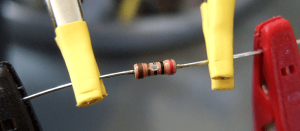
There are times when you might want an odd-value resistor. Rather than run out to the store to buy a 3,140 Ω resistor, you can get there with a good ohmmeter and a willingness to solder things in series and parallel. But when you want a precise resistor value, and you want many of them, Frankensteining many resistors together over and over is a poor solution.
Something like an 8-bit R-2R resistor-ladder DAC, for instance, requires seventeen resistors of two values in better than 0.4% precision. That’s just not something I have on hand, and the series/parallel approach will get tiresome fast.
Ages ago, I had read about trimming resistors by hand, but had assumed that it was the domain of the madman. On the other hand, this is Hackaday; I had some time and a file. Could I trim and match resistors to within half a percent? Read on to find out.
[Federico Musto], one of the Arduinos in the Arduino vs. Arduino saga (which finally came to an end last September) may have fabricated his academic record. This news comes from Wired, providing documents from the registrars at MIT and NYU stating [Musto] never attended these institutions. Since this story came out, [Musto] has edited his LinkedIn, listing his only academic credential as a kindergarten in Torino, Italy.
[shininglaser] built a tinnitus machine. What’s a tinnitus machine? It’s a device that, when activated, produces this sound: eeeeeeeeeeeeeeeeeeeeeeeeeeeeeeeeeeeeeeeeeeeeeeeeeeeeeeeeeeeeeeee. [shininglaser] built this tinnitus machine out of a pair of speakers, a cardboard box, a few batteries, and some sort of board with an epoxy-coated blob. We have no idea what the circuit looks like, but you could do this with any normal signal pulsing at around 15-18kHz (address pins on a CPU for bonus nerd cred) or a simple 555 timer.
This is a hackers bar. This bar in Roppongi, Tokyo is, “a place where you can enjoy live programming and business making…. The term ‘hacker’ is applied to someone who possesses top skills and knowledge to provide innovative and quick solutions even to the most difficult tasks.” It appears they have daily events/talks for JavaScript, Python, R, and Swift.
Captain Crunch needs our help. He’s facing some serious surgery, and even if it’s successful, there’s going to be a lot of stuff insurance doesn’t cover.
We can use Libreboot again. A few months ago, the Libreboot project left the GNU project after an issue with an employee at the Free Software Foundation. Hackaday chose not to report on this only because the accusations levied against the FSF were hearsay. I should emphasize this: the only reason we chose not to report on this is because the accusations were hearsay. Now the Libreboot project is under more democratic management and they’re working on the Thinkpad X220, the greatest Thinkpad of all time. Neat.
Here’s a quick and easy tip to get metal fume fever. Build a foundry out of a galvanized trash can! No, don’t worry about that galvanized coating, it’ll burn off. Oh, he’s doing this indoors. What’s carbon monoxide? Why am I sleepy?
In a recent post, I talked about using the “Blue Pill” STM32 module with the Arduino IDE. I’m not a big fan of the Arduino IDE, but I will admit it is simple to use which makes it good for simple things.
I’m not a big fan of integrated development environments (IDE), in general. I’ve used plenty of them, especially when they are tightly tied to the tool I’m trying to use at the time. But when I’m not doing anything special, I tend to just write my code in emacs. Thinking about it, I suppose I really don’t mind an IDE if it has tools that actually help me. But if it is just a text editor and launches a few commands, I can do that from emacs or another editor of my choice. The chances that your favorite IDE is going to have as much editing capability and customization as emacs are close to zero. Even if you don’t like emacs, why learn another editor if there isn’t a clear benefit in doing so?
There are ways, of course, to use other tools with the Arduino and other frameworks and I decided to start looking at them. After all, how hard can it be to build Arduino code? If you want to jump straight to the punch line, you can check out the video, below.
In an earlier article, I covered Fire Hazard Tests that form an important part of safety testing for electronic/electrical products. We looked at the standards and equipment used for abnormal heat, glowing wire and flame tests. A typical compliance test report for an appliance, such as a toaster, will be a fairly long document reporting the results for a large number of tests. Among these, the section for “Heat and Fire” will usually have the results of a third test – Tracking. It’s a phenomena most of us have observed, but needs some explanation to understand what it means.
What is Tracking ?
Tracking is a surface phenomena on an insulating material. When you have two conducting terminals or tracks at a high voltage (higher than 100 VAC) separated by an insulator, a combination of environmental factors such as dust, moisture and thermal cycling could cause minute leakage currents to flow on the surface between the conductors. Over time, the deposits carbonize and the surface current increases. Eventually, a carbon track forms over the surface of the insulator making it conductive at a particular “tracking” voltage. Finally, a short circuit is created between the two conductors which may also lead to fire. Worse, it’s possible that the tracking current could be lower than the rating of the protective fuse in the appliance, which will prevent the electrical supply from being cut off, creating a fire hazard. Tracking can be avoided by using the right kind of insulating materials and adequate creepage and clearance distances. One of the reasons for adding a slot between adjacent high voltage terminations or tracks on a PCB is to take care of tracking.
Test Standards
It’s impossible to conduct such tests according to real world conditions, so a standardized procedure is needed which can produce results that allow different materials to be compared. The IEC’s Technical sub-committee 15E was previously entrusted with the work of creating and maintaining tracking index methods and standards. Considering the importance of this standard and its wide implications, this work is now handled by TC 112 — Evaluation and qualification of electrical insulating materials and systems.
TC 112’s document IEC 60112 defines a “standardized method for the determination of the proof and the comparative tracking indices of solid insulating materials” for voltages up to 600 VAC, and provides information on how to design a suitable test equipment. The ASTM has an equivalent document — ASTM D3638 as does the UL — UL 746A-24. A more severe test is covered under IEC 60587 — “Electrical insulating materials used under severe ambient conditions – Test methods for evaluating resistance to tracking and erosion”. This test is often referred as the inclined plane tracking and erosion test and specifies test voltages up to 6 kV. But for now, let’s just look at the low voltage test as per IEC 60112.
Procedure
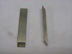
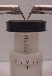
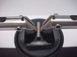
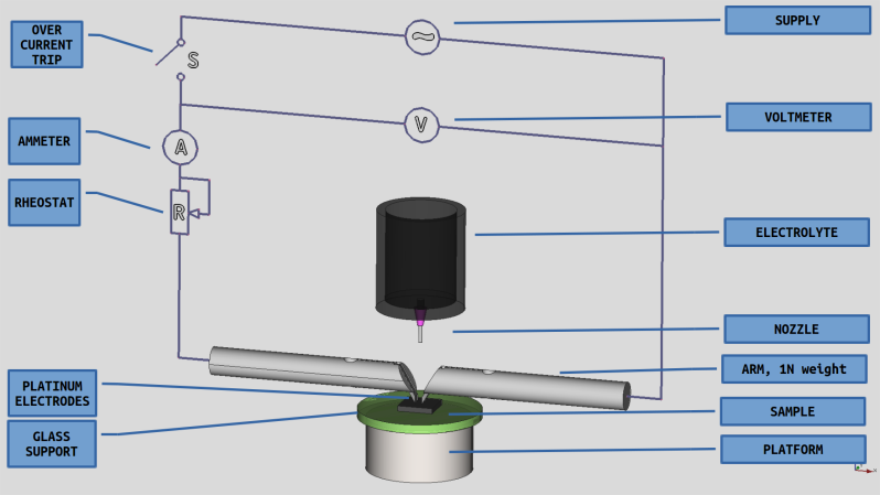
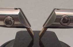
A sample of at least 20 mm x 20 mm with a minimum thickness of 3 mm is required for testing, with a set of five samples being tested each time. If the test product cannot provide a sample of these dimensions, then tiles of the insulating material need to be specifically produced using the same moulding process as used in actual production. The sample is supported on a horizontal glass platform. Two chisel-edged platinum electrodes are placed over the sample, separated by a gap of 4 mm. A voltage adjustable between 100 to 600 VAC is applied to these electrodes. The electrodes weigh down on the sample with a force of 1 N via dead weights.
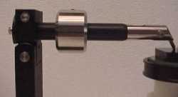
The electrical supply to the electrodes needs to be current limited. For all voltages between 100 V to 600 V, the short circuit current across the electrodes must be limited to 1 A. This is usually done by means of a series variable resistor (rheostat). In some equipment designs, the Variac (variable auto-transformer) for adjusting the voltage is mechanically coupled to the rheostat ensuring the short circuit current is always limited to 1 A. An additional, smaller value rheostat is used for minor trimming. The standard further specifies that after setting the open circuit voltage, the measured voltage at 1 A current should not drop by more than 10% (load regulation). This makes transformer design a bit tricky. At low voltages, there isn’t enough magnetic coupling between the windings, causing higher drops at lower voltages. One solution is to use two secondary windings of about 350 V each which are connected in parallel for test voltage below 300 V, and in series for higher voltages. But there are other ways of satisfying this requirement too. It’s just one example of how the designer needs to look at every requirement in the standard and then figure out how to implement it in the test equipment.
The short-circuit current is just a limiting requirement of the electrical source connected to the electrodes. The more critical setting is the “tripping” current which needs to be set to 0.5 A above which the source must be disconnected from the electrodes. The tripping sensor needs to have a time delay of two seconds before it trips and the reason for this setting will become clear a bit later.
Environmental contamination is simulated by a salt solution — usually ammonium chloride having a concentration of 0.1%. An alternate solution is prescribed for more stringent testing. While applying the test voltage across the electrodes, one drop of the electrolyte is dropped over the test sample between the electrodes every 30 seconds for a total of 50 drops. The size of each drop needs to be adjusted such that 50 drops weigh roughly 1.075 grams and 20 drops weigh 0.430 grams. This can be achieved by careful selection of the needle diameter used for the drops as well as the delivery mechanism. Some designs use a gravity feed, solenoid operated device while others use a peristaltic pump. Another way is to use an air pump which forces the liquid out of its container by forcing air in to it. The test sample passes if it survives 50 drops without triggering the over current sensor. The sample fails if the over-current sensor gets triggered or if it catches fire, at which point the electrical supply needs to be disconnected immediately.
When a drop falls over the sample across the electrodes, most of the electrical current flows through the liquid since it is conductive. This causes a current spike that quickly boils off most of the salt solution, and generally lasts for a second or two. During this two-second duration, the over-current device is programmed not to trip. With most of the water having evaporated, some of the salt is left behind as a deposit over the sample, which causes “tracking” current to flow over its surface. A while later, you will also notice some scintillation effect (sparking) as the leftover salt crystals burn out when the current flows through them.
The results of a tracking test are reported in two different ways. A Proof Tracking Index test (PTI) is usually carried out at 175 V to confirm that the sample can survive 50 drops. On the other hand, a Comparative Tracking Index test is performed over a range of voltages, incrementing the test voltage by 25 V for each succeeding test. The number of drops is always set at 50. The CTI value is determined as the highest voltage at which the sample withstands 50 drops. In some cases, the sample must also pass the test at 25 V less than the CTI voltage for a duration of 100 drops. Depending on the CTI value, the insulator is assigned a Performance Level Category with PLC0 being the highest and PLC5 being the lowest.
It’s always fascinating looking at a sample undergoing the Tracking Index Test — check out the video below. When you look at data sheets for plastic materials, the Tracking Index value will always be reported under it’s electrical properties. Paper Phenolic, which was the PCB substrate used before the advent of fibreglass, usually has a very low tracking index value (depending on its composition), ranging between 100 V to 175 V. On the other hand, depending on composition and filler materials, fibreglass substrates such as FR4 can have CTI values ranging from 175 V up to about 300 V or higher.
If you have ever seen a PCB (not the components on it), give off Magic Smoke, then you’ve seen the effects of Tracking in action. With good design, taking into consideration proper creepage and clearance distances, it is one of the failure modes which can be prevented.


 The electrical supply to the electrodes needs to be current limited. For all voltages between 100 V to 600 V, the short circuit current across the electrodes must be limited to 1 A. This is usually done by means of a series variable resistor (rheostat). In some equipment designs, the Variac (variable auto-transformer) for adjusting the voltage is mechanically coupled to the rheostat ensuring the short circuit current is always limited to 1 A. An additional, smaller value rheostat is used for minor trimming. The standard further specifies that after setting the open circuit voltage, the measured voltage at 1 A current should not drop by more than 10% (load regulation). This makes transformer design a bit tricky. At low voltages, there isn’t enough magnetic coupling between the windings, causing higher drops at lower voltages. One solution is to use two secondary windings of about 350 V each which are connected in parallel for test voltage below 300 V, and in series for higher voltages. But there are other ways of satisfying this requirement too. It’s just one example of how the designer needs to look at every requirement in the standard and then figure out how to implement it in the test equipment.
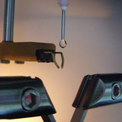 The short-circuit current is just a limiting requirement of the electrical source connected to the electrodes. The more critical setting is the “tripping” current which needs to be set to 0.5 A above which the source must be disconnected from the electrodes. The tripping sensor needs to have a time delay of two seconds before it trips and the reason for this setting will become clear a bit later.
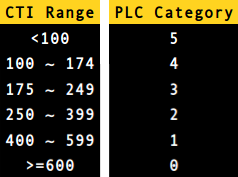 The results of a tracking test are reported in two different ways. A Proof Tracking Index test (PTI) is usually carried out at 175 V to confirm that the sample can survive 50 drops. On the other hand, a Comparative Tracking Index test is performed over a range of voltages, incrementing the test voltage by 25 V for each succeeding test. The number of drops is always set at 50. The CTI value is determined as the highest voltage at which the sample withstands 50 drops. In some cases, the sample must also pass the test at 25 V less than the CTI voltage for a duration of 100 drops. Depending on the CTI value, the insulator is assigned a Performance Level Category with PLC0 being the highest and PLC5 being the lowest.