Hackaday Links Column Banner

Hackaday Links: June 7, 2015

I’ve said over and over again that Apple’s MagSafe port is the greatest advancement in laptop tech in the last 15 years. Those charger connectors break, though, so how do you fix it? With Lego, of course (Google translatrix). Use a light-colored 1×4 brick so the LED will shine through.

Want to learn Git commands? Here’s a great game that does just that. It’s a really well-designed game/tutorial that walks you through basic Git commands.

Lets say you’re just slightly paranoid about the Bad Guys™ getting into your computer with 0-days and roller blades. You’d like to connect this computer to the Internet, but you don’t want to leave it connected all the time. The solution? A timer for an Ethernet switch. It’s actually a better solution than doing the same thing with scripts: there’s a real, physical interface, and if the Bad Guys™ get in when you are connected, they could just enable the network adapter anyway. An extremely niche use case, but that’s 99% of the security hacks we see.

The DaVinci 3D printer is an okay printer if you’re cool with the Gilette model. The filament cartridges are chipped, and the software is proprietary. These problems have been solved, and now you can use a standard RepRap heated bed and glass with the DaVinci. At this point, people are buying the DaVinci just to tear it apart.

Crowdfunding Follies: Debunking The Batteriser

It’s not on Kickstarter yet, but this product is already making its media debut, with features in all the tech blogs, an astonishing amount of print outlets, and spouted from the gaping maws of easily impressed rubes the world over. What is it? It’s the Batteriser, a tiny metal contraption that clips over AA, C, and D cells that reclaims the power trapped inside every dead battery. Yes, every dead battery you’ve ever thrown away still has up to 80% of its power remaining. Sounds like complete hogwash, right? That’s because it is.

[Dave Jones] put together a great video on the how comes and why nots of the Batteriser, and while doing so gives a great tutorial for debunking a product, heavily inspired by [Carl Sagan]’s Baloney Detection Kit. The real  debunking starts by verifying any assumptions, and the biggest fault of the Batteriser campaign is claiming 80% of a battery’s power is unused. Lucky for us, [Dave] has tons of tools and graphs to demonstrate this is not the case.

To verify the assumption that battery-powered devices will brown out after using only 20% of a battery’s available power, [Dave] does the most logical thing and looks at the data sheets for a battery. After using 20% of available power, these datasheets claim these batteries should be around 1.3V. Do devices brown out at 1.3V? Hook it up to a programmable power supply and find out.

It turns out every battery-powered device [Dave] could find worked perfectly until around 1.1V. Yes, that’s only 0.3V difference from 1.4V claimed by the patent for the Batteriser, but because of the battery discharge curve, that means 80% of the power in a normal device is already being used up. The premise of the Batteriser is invalid, and [Dave] demonstrates it’s a complete scam.

If a through debunking of the Batteriser’s claims wasn’t enough, [Dave] goes on to explain how it may actually be dangerous. The positive terminal of a battery is also the metal can, while the negative terminal is just a tiny nib of metal seperated from the rest of the battery by a gasket. Since the Batteriser is made of metal and serves as the ground for the boost converter circuit, it’s very, very close to shorting through the branding and logo emblazoned on a mylar wrapping each battery is shrouded with. One tiny nick in this insulator, and you have a direct short across the battery. That’s going to turn to heat, and there’s a lot of energy in a D cell; a failure mode for the Batteriser is a fire. That’s just terrible product design.

Video below.

Continue reading “Crowdfunding Follies: Debunking The Batteriser”

Hacklet 50 – Hydroponic Projects

Growing plants without soil has been has been amazing people for centuries. First written about in the 1600’s, hydroponics has become an industry with numerous techniques for germinating and sustaining both plant and animal life. It comes as no surprise then that hackers, makers, engineers, and scientists have been working with and improving hydroponic systems for centuries. Hydroponic plant growth is a project you can really sink your teeth into, as there’s nothing sweeter than eating the fruits and vegetables of your labor. This week’s Hacklet is all about the best hydroponic projects on Hackaday.io!

hydropwn
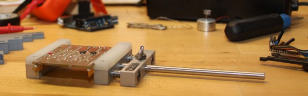
We start with HydroPWNics, [Adam Vadala-Roth’s] entry in The 2015 Hackaday Prize. [Adam] is creating a universal system with will work with both hydroponic and soil based grow systems. The hydroponic setup will consist of plants in a PVC gutter system. Water will be pumped to the top gutter, and flow down via gravity through the plant roots and back to the reservoir. The system will be monitored and controlled by a DyIO controller. Props to [mad.hephaestus] for creating DyIO, a project seeing reuse in the Hackaday.io community!


hydro2
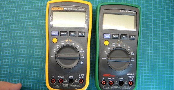
Next up is [Justin] with AAGriculture, an Automated Aquaponic Garden. AAGriculture is aquaponic system, which means it uses a symbiotic relationship between plants and fish to make more food for humans to eat. The fish in this case are bluegill and bullhead. A Raspberry Pi controls the system, while A Teensy-LC is used to help out with some of the real-time duties, like monitoring a PH probe. [Justin] is even using CO2 tanks to keep dissolved gasses in check. He must be doing something right, as his tomatoes are now over 23″ tall!


homer
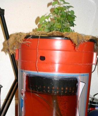
[Em] brings us 5g Aquaponics. 5g aquaponics isn’t a next generation cellular system, nor a 5.8 GHz WiFi setup, it’s an aquaponic system in a 5 Gallon bucket. Anyone from the US  will recognize the orange “Homer Bucket” from Home Depot. 5g Aquaponics includes a window, allowing the underwater workings to be monitored. Speaking of monitoring, 5g aquaponics is a manual affair – [Em] hasn’t used any electronics here. The idea is to create a system that is easy to get up and running for those who are new to Hydro/Aquaponic setups. [Em] is using a dual zone root system. The plant grows in dirt within a burlap fabric. The fabric then sits in a water bath which also houses the fish. Air pumped through an airstone keeps everything circulating. [Em’s] initial version of the project worked a bit too well. The tomato plant grew so large that the roots strangled the fish! Hopefully both flora and fauna are happy with this new rev 2.0!


smartAqua
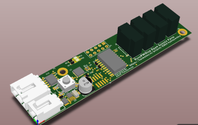
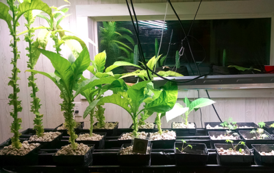
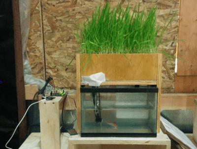
Finally we have [Kijani grows] with Smart Aquaponics, which was [Kijani’s] entry in The 2014 Hackaday Prize. One wouldn’t expect fish, plants and Linux to mix, but that is exactly what is going on here. Linux runs on the popular Wr703n router, while a custom ATmega328 Arduino compatible board keeps track of the sensors.  The second version of the system will run on an ATmega2560 and an AR9331 module, all housed on one board. The system does work, and it’s been expanded from a single fish tank to a large flood/drain table complete with grow lights, all kept at [Kijani’s] office. The biggest problems [Kijani] has run into are little things like misplaced resistors masquerading as kernel bugs.

Still haven’t eaten your veggies? Want to see more hydroponic projects? Check out our new hydroponic projects list! That’s it for this week’s Hacklet, As always, see you next week. Same hack time, same hack channel, bringing you the best of Hackaday.io!

Embed With Elliot: Multiplexing SPI Uses Few Pins

[Ralph Doncaster], aka Nerdralph, seems to be absolutely driven to see how few resources he can use on a microcontroller to get the job done. In this post on his blog, [Ralph] writes some custom bit-banged SPI code to cut the number of SPI lines necessary to drive an nRF24L01+ radio module from four down to two. That really helps if you’re using a micro with only six free pins, like an ATtiny85.

If you’re going to say, “why don’t you just buy a bigger microcontroller?”, you’re missing the point. This exercise strikes us as optimization for optimization’s sake and a dirty hack, both of which are points in its favor.  There are also a couple of techniques here for your mental toolbox. We thought it was interesting enough to look at in depth.

Continue reading “Embed With Elliot: Multiplexing SPI Uses Few Pins”

Weekly Winners: Stickvise

We’re in the middle of an epic run to award $50,000 in loot to Hackaday Prize entries this summer. This week we doled out a Stickvise low-profile PCB vise to 65 different projects! This actually started out as a really great project on Hackaday.io.

Winners are listed below, please check out their projects; skull the ones you find awesome and leave your words of encouragement as comments on those projects. Then get to work and submit something of your own. Your odds of winning during these weekly giveaways are quite good. Our recommendation for your best chances at winning are to polish up the information you’re sharing — tell the whole story of what you’ve done so far and what you plan to do. Post some images whether pictures of the prototype, renders of what you are working on, or hand-drawn diagrams from the back of a napkin.

Normally we launch the following week’s contest in this winner-announcement post. But we’re changing it up a bit this time around. Look for a post on Monday that shares all the details of what is coming next!

Last Week’s Winners of 65 Stickvise

Each project creator will find info on redeeming their prize as a message on Hackaday.io.


The 2015 Hackaday Prize is sponsored by:

Fail Of The Week: The Deadliest Multimeter

Need a good multimeter? The Fluke 17B is an excellent basic meter that will last your entire career. It’s also $100 USD. Need something cheaper? Allow me to introduce the AIMOmeter MS8217. On the outside, it’s a direct copy of the Fluke 17b, right down to the screen printing but understandably lacking the yellow enclosure. $30 USD will get you an exact copy of a Fluke 17B, it would seem. Right? Not a chance. [electronupdate] did a teardown of the AIMOmeter, and while this meter looks like a Fluke on the outside, it’s probably going to kill somebody.

The teardown begins with a look at the ratings on the back of this off-brand meter. It does have two fuses, but the engraving on the back strangely claims ‘Wrrebt insurance limit’. If anyone has any idea what a ‘wrrebt’ is, please leave a note in the comments. The only references to this word in Google are mis-OCRed blackletter type in a book from the early 1800s.

Opening up the meter reveals – surprisingly – two real fuses in the meter. There were no markings on the bigger fuse, which could be a problem for verifying if the fuse is of the proper value. That’s not really a problem, though: the fuse isn’t even between ground and the amp probe socket. Yes, this fuse is completely useless, and testing the resistance with the fuse out of the circuit confirms this.

After putting the meter back together, [electron] tests the accuracy of the meter. With a 1 mA current source, the mA setting seems to work, but when testing the larger Amp range of this meter, the results display in milliVolts. Don’t worry, there’s an easy fix for that: just press the dial down just right and the correct setting will be displayed. Wow.

You get what you pay for, and if you only ever use an AIMOmeter for measuring Arduinos and batteries, you might – might – be alright. This is not the kind of meter you want to measure line voltage, motors, or anything else with, though.

Retrotechtacular: Cover Your CONUS With OTH-B Radar

If you’re a ham, you already know that the ionosphere is a great backboard for bouncing HF signals around the globe.  It’s also useful for over-the-horizon backscatter (OTH-B (PDF)) radar applications, which the United States Air Force’s Rome Laboratory experimented with during the Cold War.

During the trial program, transmit and receive sites were set up ninety miles apart inside the great state of Maine. The 1/2 mile-long transmit antenna was made up of four arrays of twelve dipole elements and operated at 1MW. An antenna back screen and ground screen further expanded the signal’s range. Transmission was most often controlled by computers within the transmit building, but it could also be manually powered and adjusted.

The receive site had 50-ft. antenna elements stretching 3900 feet, and a gigantic ground screen covering nearly eight acres. Signals transmitted from the dipole array at the transmit site bounced off of the ionosphere and down to the receive site. Because of step-scanning, the system was capable of covering a 180° arc. OTH-B radar systems across the continental United States were relegated to storage at the end of the Cold War, but could be brought back into service given enough time and money.

Continue reading “Retrotechtacular: Cover Your CONUS With OTH-B Radar”