When somebody tackles an engineering problem, there are two possible paths: they can throw together a quick and dirty fix that fits their needs (the classic “hack”, as it were), or they can go the extra mile to develop a well documented solution that helps the community as a whole. We cover it all here at Hackaday, but we’ve certainly got a soft spot for the latter approach, even if some may feel it falls into the dreaded territory of “Not A Hack”.
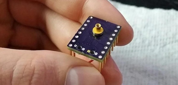
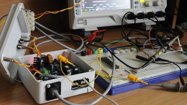
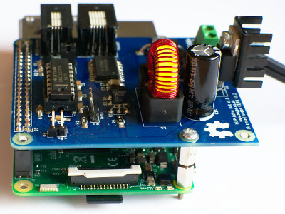 When [Gary Preston] wanted to control his telescope and astrophotography hardware, he took the second path in a big way. Over the course of several posts on his blog, [Gary] walks us though the creation of his open source Raspberry Pi add-on board that controls a laundry list of sensors and optical gear. Just don’t call it a HAT, while it may look the part, [Gary] is very specific that it does not officially meet the HAT specifications put out by the Raspberry Pi Foundation.
Even if you aren’t terribly interested in peering into the infinite void above, the extremely detailed write-up [Gary] has done contains tons of multidisciplinary information that you may find useful. From showing how to modify the Pi’s boot configuration to enable true hardware UART (by default, the Pi 3 ties it up with Bluetooth) and level shifting it with a ST3232 to a breakdown of the mistakes he made in his PCB layout, there’s plenty to learn.
Astro CAT is a completely open source project, with the hardware side released under the CERN Open Hardware License v1.2, and the INDI driver component is available under the GPL v3.
If this looks a bit daunting for your first stab at astrophotography with the Raspberry Pi, fear not. We’ve covered builds which can get you up and running no matter what your budget or experience level is.