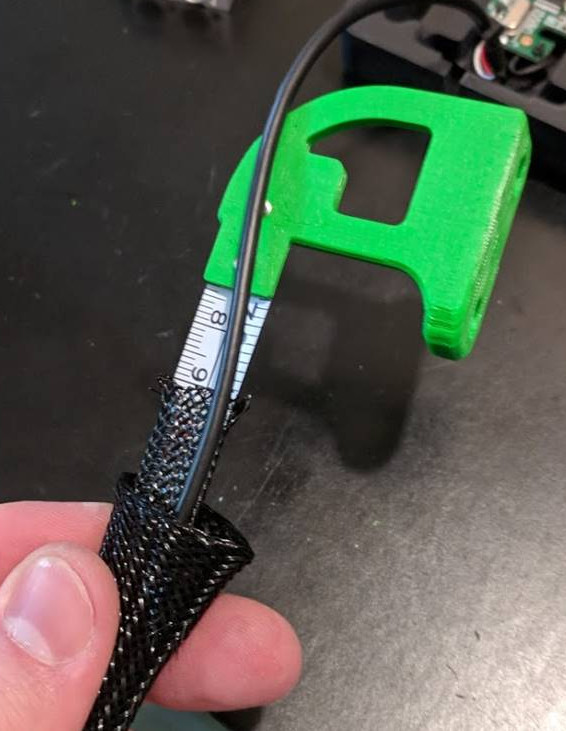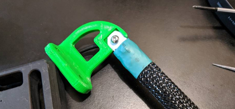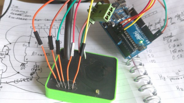
Aluminum extrusions are a boon for mechanical assemblies, but they require a stock of brackets and other hardware to be kept on hand. [mightynozzle] has decided to make things a little easier for prototyping and low-stress assemblies by creating a collection of 3D printable brackets for aluminum extrusions. 3D printing your own bracket hardware means faster prototyping, and if the assemblies don’t need the extra strength and rigidity of metal brackets you can just stick with the 3D printed versions.
This project showcases two things well. The first is that while brackets are not particularly expensive or hard to obtain, it can still be worth 3D printing them to reduce the overall amount of hardware one needs to keep on hand to make prototyping faster. The other is that 3D printing can shine when it comes to the creation of things like brackets: a few dimes’ worth of plastic can be turned into precise yet geometrically simple objects that would be a pain to make by other means. It certainly beats sitting on one’s hands waiting for parts to be delivered.
Previously, we discussed how to apply the most basic hypothesis test: the z-test. It requires a relatively large sample size, and might be appreciated less by hackers searching for truth on a tight budget of time and money.
As an alternative, we briefly mentioned the t-test. The basic procedure still applies: form hypotheses, sample data, check your assumptions, and perform the test. This time though, we’ll run the test with real data from IoT sensors, and programmatically rather than by hand.
The most important difference between the z-test and the t-test is that the t-test uses a different probability distribution. It is called the ‘t-distribution’, and is similar in principle to the normal distribution used by the z-test, but was developed by studying the properties of small sample sizes. The precise shape of the distribution depends on your sample size. Continue reading “Statistics And Hacking: A Stout Little Distribution”→
If you only have a car and you need to unsolder some tricky surface mount components: what would you do? If you’re Kasyan TV, you’d remove your car’s halogen lights and get to town. That’s right: car lights for reflow.
When the friend of the host of Kasyan TV needed to remove some roasted toasted FETs from his motherboard but didn’t have anything for reflowing, she took some headlights and used them as an infrared source to desolder the FETs. Powered by a lab supply (although car batteries work too), the process works with 60 and 100-watt bulbs.
Now, reflowing with halogen bulbs isn’t new, and we’ve seen it done with the run of the mill 100-watt bulbs and a halogen floodlight. However, what we really like about using car lights is that they’re available everywhere and we already own some that we could (temporarily) repurpose. Now, don’t get us wrong – if you’re going to be reflowing more than just a little, there are plenty of alternative methods that don’t involve staring at “rather bright lights” for extended periods of time.
A lot of the DIY laser engravers and cutters we cover here on Hackaday are made with laser diodes salvaged from Blu-ray drives and projectors, which are visible lasers in the 400 – 450nm range (appearing as violet or blue). Unfortunately there is an upper limit in terms of power on visible diode lasers, most builds max out at 5W or so. If you need more power than that, you’ll likely find yourself looking at gas laser cutters like the K40. While the K40 is a great starting point if you’re looking to get into “real” lasers, it’s a very different beast from the homebrew builds using visible lasers.
With a gas laser the beam itself is invisible, making it much more difficult to align or do test runs. One solution is to add a visible laser to the K40 which can be used to verify alignment, but making sure it’s traveling down the same path as the primary laser usually requires an expensive beam combiner. Looking to avoid this cost, [gafu] wanted to see if it was possible to simply move the visible laser into the path of the primary beam mechanically.
An adjustable microswitch detects when the lid has been opened.
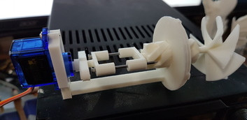
In the setup that [gafu] has come up with, a cheap laser module (the type from a handheld laser pointer) is moved into the path of the primary laser on an arm that’s actuated by a simple hobby servo. To prevent the primary and visible lasers from firing at the same time, an Arduino is used to control the servo given the current state of the K40’s lid. If the lid of the K40 is open, the primary laser is shutoff and the visible laser is rotated into position so the operator can see where the primary laser’s beam would be hitting. Once the lid is closed, the visible laser rotates out of the way and the primary is powered back up.
Running the cutting or engraving job with the lid of the K40 machine open now let’s [gafu] watch a “dry run” of the entire operation with the visible laser before finally committing to blasting the target with the full power beam.
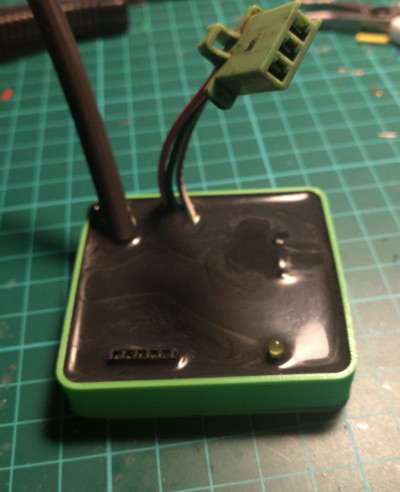
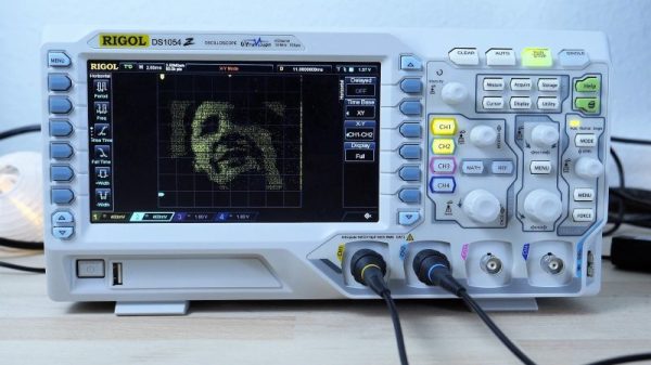
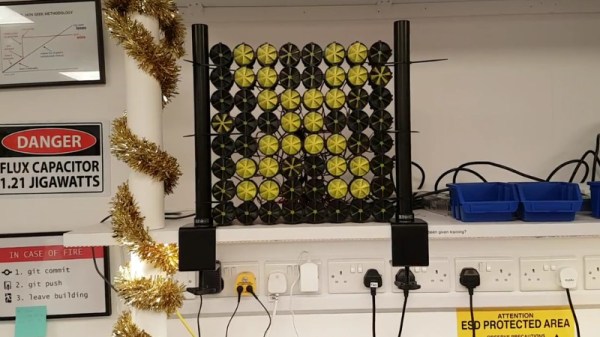
Mike Harrison, perhaps better known to us as the titular Mike of YouTube channel mikeselectricstuff, is a hardware hacking genius. He’s the man behind this year’s Superconference badge, and his hacks and teardowns have graced our pages many times. The best thing about Mike is that his day job is designing implausibly cool one-off hardware for large-scale art installations. His customers are largely artists, which means that they just don’t care about the tech as long as it works. So when he gets together with a bunch of like-minded hacker types, he’s got a lot of pent-up technical details that he just has to get out. Our gain.
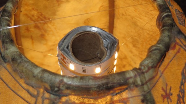
He’s been doing a number of LCD installations lately. And he’s not using the standard LCD calculator displays that we all know and love, although the tech is exactly the same, but is instead using roughly 4″ square single pixels. His Superconference talk dives deep into the behind-the-scenes cleverness that made possible a work of art that required hundreds of these, suspended by thin wires in mid-air, working together to simulate a flock of birds. You really want to watch this talk.
Traditional desktop 3D printing technology has effectively hit a wall. The line between a $200 and a $1000 printer is blurrier now than ever before, and there’s a fairly prevalent argument in the community that you’d be better off upgrading two cheap printers and pocketing the change than buying a single high-end printer if the final results are going to be so similar.
As anyone who’s pushed their 3D printer a bit too hard can tell you, the first thing that usually happens is the extruder begins to slip and grind the filament down. As the filament is ground down it starts depositing plastic on the hobbed gear, further reducing grip in the extruder and ultimately leading to under-extrusion or a complete print failure. To address this issue, MIT’s printer completely does away with the “pinch wheel” extruder design and replaces it with a screw mechanism that pulls special threaded filament down into the hot end. The vastly increased surface area between the filament and the extruder allows for much higher extrusion pressure.
An improved extruder doesn’t do any good if you can’t melt the incoming plastic fast enough to keep up with it, and to that end MIT has pulled out the really big guns. Between the extruder and traditional heater block, the filament passes through a gold-lined optical cavity where it is blasted with a pulse modulated 50 W laser. By closely matching the laser wavelength to the optical properties of the plastic, the beam is able to penetrate the filament and evenly bring it up to nearly the melting point. All without physically touching the filament and incurring frictional losses.
There are still technical challenges to face, but this research may well represent the shape of things to come for high-end printers. In other words, don’t expect a drop-in laser hot end replacement for your $200 printer anytime soon; the line is about to get blurry again.
Here’s a slightly different way to check on the status of your laundry. Instead of checking if the machine is vibrating, or listening for sound, or pulling everything apart and hacking an ESP8266 into it, check the power that the machine is drawing. This is what [Scrand] did in his IoT dryer build.
The secret behind the hack is the Sonoff POW, a small device that sits in between the wall and the dryer. It has a relay in it that controls it, but, importantly for this hack, it’s able to measure the power consumption used by what’s plugged into it. By installing the ESPurna firmware on it, he can now use all the power of the firmware to control and monitor what’s connected to the POW. He wrote a PowerShell script to monitor the http server now running on the POW checking on how much power is being drawn by the dryer. When that power drops, the laundry is done, and in the case of [Scrand], a text is sent saying so.
When you’re sitting on the couch relaxing, why get up every five minutes to check your laundry when you can have it text you when you know it’s done? Then you can decide whether to get up and deal with it or just leave it until later. The whole reason ESPurna exists to begin with is to check on the status of the laundry. Or, you can go a bit overboard with this laundry room monitor.