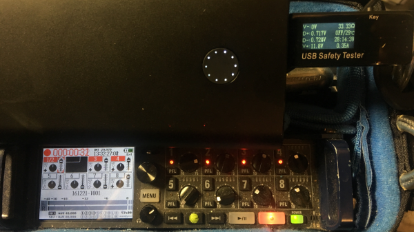
[Robert Nixdorf] frequently needs to use this high-end audio recorder, but it sucks dry a set of eight AA batteries in just a few hours. Obviously a longer lasting solution was required, and he started scouring the web looking for an answer. He bought a Quick Charge power bank and then hacked a Digispark to negotiate with the power bank to provide 12V output to Quick Charge his audio recorder.
Qualcomm’s Quick Charge system is designed to provide increased output voltages to reduce charging time in QC compatible devices such as mobile phones powered by their Snapdragon range of SoC’s. Depending on how the end-point negotiates with the charger, either 5V, 9V or 12V outputs are supported.
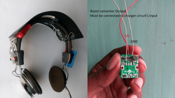
You can dig into the details in Qualcomm’s Quick Charge Patent [PDF] which shows how the system works. Quite simply, the voltage provided by the charger depends on the signals set on the D+ and D- data pins during the initial handshaking phase. [Robert] found it easy to get his QC charger to provide the required voltage by using a 3V3 voltage regulator and a resistive divider. But a more permanent solution would be needed if he wanted to use it on the field.
His parts bin revealed a Digispark board and he set about hacking it. He isolated the VUSB from the rest of his board since it would get pulled up to 12V when in use. And then replaced the existing 5V regulator with a 3V3 one. This required several bodges which he has documented on his blog. Some simple code flashed on the ATtiny85 handles all of the handshaking and sets up 12V output to run his audio recorder. A single charge on the power bank now lasts him almost 12 hours, so he’s pretty satisfied with the hack.
Quick Charge is currently at version 4 and supports USB-C and USB-PD hardware such as cables and connectors. But it seems using USB-C hardware outside of the current USB-C specifications is deprecated, with reports suggesting Google is asking OEM’s not to use Quick Charge but stick to USB-PD. Let’s hope this gets settled one way or another soon.
Thanks, [Frank] for the tip.
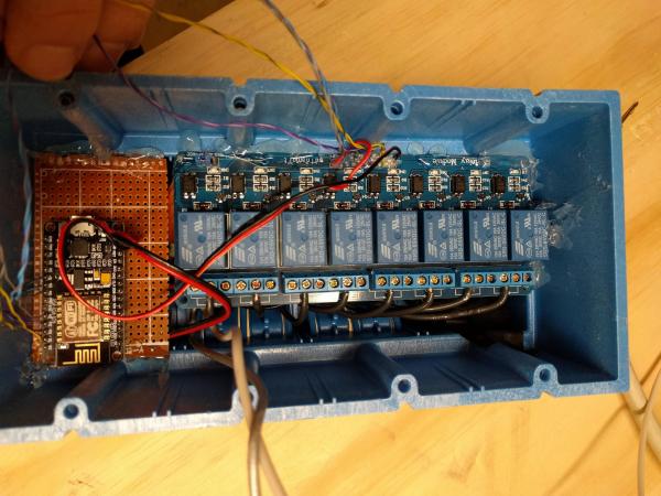
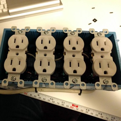 Inside the junction box, an eight-channel relay is connected to an ESP8266 module. The module uses MQTT to communicate with Home Assistant and is powered by a partially dismembered USB AC adapter — wrapped in kapon tape for safe-keeping. The entire bar is wired through a 10A fuse, while also using a fire resistant 4-gang electrical box. Once the outlets were wired in, closing it up finished up the power bar.