PTC Heaters For Reflow Soldering

Reflow soldering – setting components on a PCB in blobs of solder paste and heating the whole assembly at once to melt all joints simultaneously – has been the subject of many ingenious hacks. Once it was the sole preserve of industrial users with specialist microprocessor-controlled ovens, now there are a myriad Arduino-controlled toaster ovens, hot air blowers, and hotplates that allow hackers and makers to get in on the reflow act too.

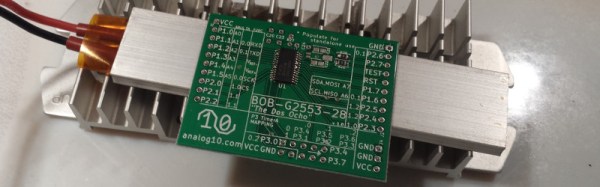
This morning a fresh idea in the reflow soldering arena has come our way. It’s not the most earth-shattering, but it does have some advantages so is worth a second look. [Analog Two] has successfully used a PTC heating element as a reflow soldering hotplate.

PTC heating elements are thermistors with a positive temperature coefficient. As their temperature rises, so does their electrical resistance. By careful selection of materials they can be manufactured with a sharp increase in resistance at a particular temperature. Thus when an electrical current is passed through them they heat up until they reach that temperature, then the current decreases as the resistance goes up, and they do not heat beyond that point. Thus as heaters they are intrinsically self-regulating. From our point of view they have another advantage, they are also cheap. Fitted as they are to thousands of domestic heating products they are readily available, indeed [Analog Two] found his on Amazon.

The heater chosen was a 200W 110V model with a temperature of 230 Celcius to match the solder he was using. They are also available for other mains voltages, and even at 12 and 24V for automotive applications. He reports that the time to reflow was about 90 seconds.

We’ve mentioned the advantages of this heater as its price and regulated temperature. Looking at the pictures though a disadvantage is its size. This is a reflow plate for small boards. There are larger PTC heater elements available though, it would be interesting to hear people’s experiences reflowing with them.

Hotplates for reflow soldering have featured before a few times here at Hackaday. We recently had this tiny plate, but we’ve also had a PID-controlled plate, and an Arduino-controlled domestic hotplate. We’re sure this is an avenue with further to go.

After The Prize: SatNOGS Builds Satellites

When Hackaday announced winners of the 2014 Hackaday Prize, a bunch of hackers from Greece picked up the grand prize of $196,418 for their SatNOGS project – a global network of satellite ground stations for amateur Cubesats.

upsat-integration-test-1The design demonstrated an affordable ground station which can be built at low-cost and linked into a public network to leverage the benefits of satellites, even amateur ones. The social implications of this project were far-reaching. Beyond the SatNOGS network itself, this initiative was a template for building other connected device networks that make shared (and open) data a benefit for all. To further the cause, the SatNOGS team set up the Libre Space Foundation, a not-for-profit foundation with a mission to promote, advance and develop Libre (free and open source) technologies and knowledge for space.

Now, the foundation, in collaboration with the University of Patras, is ready to launch UPSat – a 2U, Open Source Greek Cubesat format satellite as part of the QB50 international thermosphere research mission. The design aims to be maximally DIY, designing most subsystems from scratch. While expensive for the first prototype, they hope that documenting the open source hardware and software will help kickstart an ecosystem for space engineering and technologies. As of now, the satellite is fully built and undergoing testing and integration. In the middle of July, it will be delivered to Nanoracks to be carried on a SpaceX Dragon capsule and then launched from the International Space Station.

Continue reading “After The Prize: SatNOGS Builds Satellites”

Hackaday’s Fun With International Mains Plugs And Sockets

When we recently covered the topic of high voltage safety with respect to mains powered equipment, we attracted a huge number of your comments but left out a key piece of the puzzle. We take our mains plugs and sockets for granted as part of the everyday background of our lives, but have we ever considered them in detail? Their various features, and their astonishing and sometimes baffling diversity across the world.

When you announce that you are going to talk in detail about global mains connectors, it is difficult not to have an air of Sheldon Cooper’s Fun With Flags about you. But jokes and the lack of a co-starring Mayim Bialik aside, there is a tale to be told about their history and diversity, and there are also lessons to be taken on board about their safety. Continue reading “Hackaday’s Fun With International Mains Plugs And Sockets”

Working With Mains Voltage: The Electrifying Conclusion!

This is the second in a two-part series looking at safety when experimenting with mains-voltage electronic equipment, including the voltages you might find derived from a mains supply but not extending to multi-kilovolt EHT except in passing. In the first part we looked at the safety aspects of your bench, protecting yourself from the mains supply, ensuring your tools and instruments are adequate for the voltages in hand, and finally with your mental approach to a piece of high-voltage equipment.

The mental part is the hard part, because that involves knowing a lot about the inner life of the mains-voltage design. So in this second article on mains voltages, we’ll look into where the higher voltages live inside consumer electronics.

Continue reading “Working With Mains Voltage: The Electrifying Conclusion!”

A Dis-Integrated 6502

The 6502 is the classic CPU. This chip is found in the original Apple, Apple II, PET, Commodore 64, BBC Micro, Atari 2600, and 800, the original Nintendo Entertainment System, Tamagotchis, and Bender Bending Rodriguez. This was the chip that started the microcomputer revolution, and holds a special place in the heart of every nerd and technophile. The 6502 is also possibly the most studied processor, with die shots of polysilicon and metal found in VLSI textbooks and numerous simulators available online.

The only thing we haven’t seen, until now, is a version of the 6502 built out of discrete transistors. That’s what [Eric Schlaepfer] has been working on over the past year. It’s huge – 12 inches by 15 inches – has over four thousand individual components, and so far, this thing works. It’s not completely tested, but the preliminary results look good.

The MOnSter 6502 began as a thought experiment between [Eric] and [Windell Oskay], the guy behind Evil Mad Scientist and creator of the discrete 555 and dis-integrated 741 kits. After realizing that a few thousand transistors could fit on a single panel, [Eric] grabbed the netlist of the 6502 from Visual6502.org. With the help of several scripts, and placing 4,304 components into a board design, the 6502 was made dis-integrated. If you’re building a CPU made out of discrete components, it only makes sense to add a bunch of LEDs, so [Eric] threw a few of these on the data and address lines.

This is the NMOS version of the 6502, not the later, improved CMOS version. As such, this version of the 6502 doesn’t have all the instructions some programs would expect. The NMOS version is slower, more prone to noise, and is not a static CPU.

So far, the CPU is not completely tested and [eric] doesn’t expect it to run faster than a few hundred kilohertz, anyway. That means this gigantic CPU can’t be dropped into an Apple II or commodore; these computers need a CPU to run at a specific speed. It will, however, work in a custom development board.

Will the gigantic 6502 ever be for sale? That’s undetermined, but given the interest this project will receive it’s a foregone conclusion.

Correction: [Eric] designed the 555 and 741 kits

Making A Fixed Voltage Power Supply Adjustable

Switch-mode power supplies are ubiquitous. Standard off-the-shelf modules in a consistent range of form factors available from multiple manufacturers. Globalized manufacturing and trade has turned them from expensive devices into commodity parts, and they long ago replaced iron-cored transformers as the go-to choice when a high-current low-voltage mains supply is required.

[Lindsay Wilson] faced a power supply problem for a motor he was working with, it required 7.4V and no off-the-shelf power supplies were to be found with that voltage. His solution was to take a 12V supply and modify it to deliver a variable voltage so he could dial in his requirement. A Chinese-made 12v 33A switch-mode supply was purchased, and he set to work.

In the event he was able to design a replacement feedback divider incorporating a rotary potentiometer, and achieve a voltage range of 5 to 15V. A small LED voltmeter mounted next to it in the PSU case gave him a very neat result.

Modifying a switch-mode supply to deliver a different voltage is a well-worn path we’ve covered at least once before. What makes Lindsay’s article worth a read is his reverse-engineering and examination in detail of the PSU circuit. If you’d like to learn more about all the different facets of design that go into a switch-mode PSU, it’s a detailed yet readable primer. We’d suggest reading our recent series on mains and high voltage safety before cracking open a switch-mode PSU yourself, but even if you’re never going to do it there’s something to be gained from knowing in detail how they work.

We’ve featured [Lindsay]’s work here at Hackaday a few times over the years. Check out his ultrasonic transducer power supply, which might be of use were you were building the ultrasonic soldering iron we featured not long ago, his laser stripping of ribbon cables, and his tale of decapping a USB isolator chip.