A Sneak Peek At Anechoic Chamber Testing

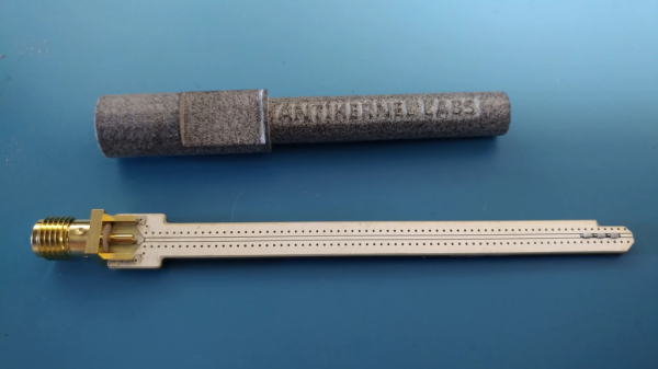
[Mathieu Stephan] has something new in the works, and while he isn’t ready to take the wraps off of it yet, he was kind enough to document his experience putting the mysterious new gadget through its paces inside an anechoic chamber. Considering the majority of us will never get inside of one of these rooms, much less have the opportunity to test our own hardware in one, he figured it was the least he could do.

If you’re not familiar with an anechoic chamber, don’t feel bad. It’s not exactly the sort of thing you’ll have at the local makerspace. Put simply it’s a room designed to not only to remove echos on the inside, but also be completely isolated from the outside. But we aren’t just talking about sound deadening, the principle can also be adapted to work for electromagnetic waves. So not only is in the inside of the anechoic chamber audibly silent, it can also be radio silent.

This is important if you want to test the performance of things like antennas, as it allows you to remove outside interference. As [Mathieu] explains, both the receiver and transmitter can be placed in the chamber and connected to a vector network analyzer (VNA). The device is able to quantify how much energy is being transferred between the two devices, but the results will only be accurate if that’s the only thing the VNA sees on its input port.

[Mathieu] can’t reveal images of the hardware or the results of the analysis because that would give too much away at this point, but he does provide the cleverly edited video after the break as well as some generic information on antenna analysis and the type of results one receives from this sort of testing. Our very own [Jenny List] has a bit more information on the subject if you’d like to continue to live vicariously through the accounts of others. For the rest of us, we’ll just have to settle for some chicken wire and a wooden crate.

Continue reading “A Sneak Peek At Anechoic Chamber Testing”

Choosing Cell Modems: The Drama Queen Of Hardware Design

So you went to a tradeshow and heard about this cool new idea called the Internet Of Things; now it’s time to build an IoT product of your own. You know that to be IoT, your Widget D’lux® has to have a network connection but which to choose?

You could use WiFi or Bluetooth but that would be gauche. Maybe LoRaWAN? All the cool kids are using LoRa for medium or long range wireless these days, but that still requires a base station and Widget D’lux® will be a worldwide phenomenon. Or at least a phenomenon past your bedroom walls. And you know how much user’s hate setting things up. So a cell modem it is! But what do you have to do to legally include one in your product? Well that’s a little complicated.

Continue reading “Choosing Cell Modems: The Drama Queen Of Hardware Design”

The Value Of Cardboard In Product Design

A while ago, [Eric Strebel] created a backpack hanger. The result was great — by just bolting this backpack hanger to the wall, he kept his backpack off the floor and out of the way. There was even a place for him to set his phone to charge. [Eric] is thinking about turning this idea into a product, and just posted a video on his process of making a cardboard mockup.

Since this is a study in industrial design, any mockup will need to keep in mind how the finished article will be constructed. In this case, [Eric] is going to use 4-5mm thick aluminum, cut on a water jet, bent into place, and finally anodized. The finished product will be made out of bent sheet aluminum, so this little bit of product design will use Matboard — a thick, heavy cardboard often used for mounting pictures in frames. The Matboard will substitute for the aluminum, as it is carefully cut, bent, and glued into shape.

The tools for this build are simple, just a hobby knife, razor blade, ruler, and a pen. But there are a few tricks to working with Matboard. To bend these pieces perfectly, [Eric] is painting one side with water. This loosens the fibers in the Matboard, allowing for perfect creases before one layer of the build is glued together.

Once a few layers of this Matboard are glued together, the finished product becomes less like cardboard and more like a very soft wood. This allows [Eric] to use belt sanders and countersink drill bits to give a little bit of polish to this one-off prototype. This finished article works great, and now [Eric] is looking at taking this idea into production.

Continue reading “The Value Of Cardboard In Product Design”

A Daylight-Readable Bar Graph Display In The 70s Wasn’t Cheap

The driver board with display attached; the row of lamps is visible on the right hand side.

LEDs weren’t always an easy solution to displays and indicators. The fine folks at [Industrial Alchemy] shared pictures of a device that shows what kind of effort and cost went into making a high brightness bar graph display in the 70s, back when LEDs were both expensive and not particularly bright. There are no strange materials or methods involved in making the display daylight-readable, but it’s a peek at how solving problems we take for granted today sometimes took a lot of expense and effort.

The display is a row of 28 small incandescent bulbs, mounted in a PCB and housed in a machined aluminum frame. Holes through which to view the bulbs are on both the top and front of the metal housing, which allows the unit to be mounted in different orientations. It was made as a swappable module, its 56 machined gold pins mate to sockets on the driver board. The driver board itself consists of 14 LM119 dual comparators, each of which controls two bulbs on the display.

An example of a Wamco minitron bar graph display. Each window contains an incandescent filament. [Source: industrialalchemy.org]
[Industrial Alchemy] believes that the display unit itself may have been a bit of a hack in its own way. Based on the pin spacing and dimensions of the driver board, they feel that it was probably designed to host a row of modular units known as the Wamco minitron bar graph display. An example is pictured here; they resembled DIP chips and could be stacked side-by-side to make a display of any length. Each window contained an incandescent filament in a reflective well, and each light could be individually controlled.

These minitron bar graph units could only be viewed from the top, and were apparently high in cost and low in availability. Getting around these limitations may have been worth creating this compatible unit despite the work involved.

Display technology has taken many different turns over the years, and you can see examples of many of them in one place in the Circus Clock, which tells the time with a different technology for each digit: a nixie, a numitron, a 7-segment thyratron tube, a VFD, an LED dot display, and a rear projection display.

What Good Are Counterfeit Parts? Believe It Or Not, Maybe A Refund

[Charles Ouweland] purchased some parts off Aliexpress and noticed that the Texas Instruments logo on some of his parts wasn’t the Texas Instruments logo at all, it was just some kind of abstract shape that vaguely resembled the logo. Suspicious and a little curious, he decided to take a closer look at the MCP1702 3.3v LDO regulators he ordered as well. Testing revealed that they were counterfeits with poor performance.

Left: counterfeit part. Right: genuine Microchip MCP1702-3302

Looking at the packages, there were some superficial differences in the markings of the counterfeit MCP1702 versus genuine parts from Microchip, but nothing obviously out of place. To conclusively test the devices, [Charles] referred to Microchip’s datasheet. It stated that the dropout voltage of the part should be measured by having the regulator supply the maximum rated 250 mA in short pulses to avoid any complications from the part heating up. After setting up an appropriate test circuit with a 555 timer to generate the pulses for low duty cycle activation, [Charles] discovered that the counterfeit parts did not meet Microchip specifications. While the suspect unit did output 3.3 V, the output oscillated badly after activation and the dropout voltage was 1.2 V, considerably higher than the typical dropout voltage of 525 mV for the part, and higher even than the maximum of 725 mV. His conclusion? The parts would be usable in the right conditions, but they were clearly fakes.

The usual recourse when one has received counterfeit parts is to dump them into the parts bin (or the trash) and perhaps strive to be less unlucky in the future, but [Charles] decided to submit a refund request and to his mild surprise, Aliexpress swiftly approved a refund for the substandard parts.

While a refund is appropriate, [Charles] seems to interpret the swift refund as a sort of admission of guilt on the part of the reseller. Is getting a refund for counterfeit parts a best-case outcome, evidence of wrongdoing, or simply an indication that low value refund requests get more easily approved? You be the judge of that, but if nothing else, [Charles] reminds us that fake parts may be useful for something perhaps unexpected: a refund.

Raspberry Pi PoE Redux

[Martin Rowan] was lucky enough to get his hands on the revised Power Over Ethernet (PoE) hat for the Raspberry Pi. Lucky for us, he wrote it up for our benefit, including inspection of the new hat, it’s circuit, and electrical testing to compare to the original hardware.

You may remember the original release of the PoE hat for the Raspberry Pi, as well as the subsequent recall due to over-current issues. In testing the revised board, [Martin] powered a test load off the USB ports, and pulled over an amp — The first iteration of the PoE hat would often trip the over-current protection at 300 milliamps.

This afternoon, the redesigned PoE board was officially released, and the post mortem of the problem documented in a blog post. It’s a lesson in the hidden complexity of hardware design, as well as a cautionary tale about the importance of thorough testing, even when the product is late and the pressure is on.

The PoE hat converts 48 volt power down to a 5 volt supply for the Pi using a flyback transformer. The problem was that this transformer setup doesn’t deliver clean steady 5 volt power, but instead provides power as a series of spikes. While these spikes were theoretically in spec for powering the Pi and usb devices, some Raspberry Pis were detecting those spikes as too much current pushed through the USB ports. The official solution essentially consists of better power filtering between the hat and the Pi, flattening that power draw.

We’re looking forward to getting our hands on this new and improved PoE Hat, and using it in many project to come.

The Negative Rail Explained

With the high availability of modular components and incredible wealth of information and tutorials online, it’s now easier than ever for hackers and makers to assemble complex electronic projects without getting bogged down with the theory behind it all. But the downside is that the modern electronic hobbyist often doesn’t have as deep an understanding of the low-level concepts that they would have if they had to build everything from scratch. This can be a problem when they try diagnosing and repairing faults, or when they start to branch out into reverse engineering.

Which makes “Building Blocks” by [David Christensen] a very compelling series. Every week he will be demonstrating a new circuit on his blog, complete with a plain English explanation of how and why it’s used. In this first installment of the series, he’s tackling a concept most of us have seen when poking around in more complex electronic devices, but maybe never really gave much thought to: the negative rail.

What exactly is the negative rail, anyway? It’s pretty easy to understand the positive rail in a circuit and its relation to ground; even multiple positive rails, such as in devices which use both 5 V and 3.3 V, are simple enough to wrap your head around. Unfortunately when something drops below that logical 0V reference, it isn’t quite as intuitive. But as [David] explains, the negative rail in a circuit is critical for dealing with bipolar signals, such as audio, which ride above and below the 0 V center point.

[David] goes over a few methods used to create the negative rail, from the classic center-tap transformer to using a buck-boost converter. But not content with just describing how these circuits work, he walks the reader through the creation of a charge pump circuit that you can drop into your next project if you find yourself in need of the elusive voltage. After explaining and diagramming it, he builds the circuit on a scrap piece of copper clad board and puts it through some benchmarks to prove it matches the theory he laid out.

If you’re in the mood for more negative talk, check out the battle our very own [Steven Dufresne] had with voltages of varying polarity when building his BB-8 robot.