For many environmental enthusiasts, horizontal-axis wind turbines (HAWTs) — the kind that look like windmills slowly spinning in the distance — are a pretty familiar sight. Unfortunately, there are quite a few caveats that make them harder to adopt despite the fact that harvesting renewable energy sources is more sustainable than relying on natural gas and fuels that can be depleted. Since they face in one axis, they need to be able to track the wind, or else trade off the ability to maximize energy output. In turbulent and gusty conditions, as well, HAWTs face accelerated fatigue when harvesting.
The development of the vertical-axis wind turbine (VAWT) solves several of these issues. In addition, the turbines are typically closer to the ground and the gearbox replacement is simpler and more efficient. Maintenance is more accessible due to the size of the turbines, so no heavy machinery is typically necessary to access crucial components on-site. In addition, the gearbox by nature of its operation takes on less fatigue and is able to function in turbulent winds, which reduces the rate of failure.


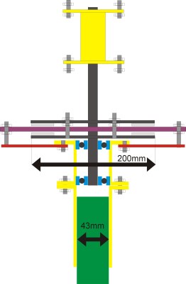
For a simple version of a VAWT that you can build yourself, [BlueFlower] has published several mechanical drawings that detail the layout of the design. The wind power generator uses 24 magnets, copper wire fashioned into coils, and a metal plate for the main generator. The coils are arranged in a circular formation on a static plate, while the magnets are equally spaced on a moving circular plate. As the magnets pass over coils, the flux induces a current, which increases as the plates spin faster.
The blades of the generator are made from blue foam with a metal bar running through it for structure. Three of the blades are attached with triangular bars to a central rod, which also holds the spinning magnetic plate.
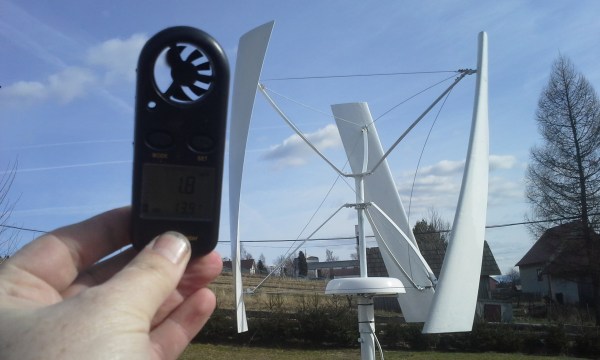
In [BlueFlower]’s initial trials using the VAWT for charging a battery they were able to generate a max power of 15W on boost mode and 30-70W when charging in PWM mode. Not bad for a home-made wind power generator!
There aren’t only pros to the design, however. While VAWTs may be cheaper, more mobile, and more resistant to wear and tear, there are some design features that prevent the generators from functioning as well as HAWTs at harvesting energy. The blades don’t produce torque at the same time, with some blades simply being pushed along. This produces more drag on the blades when they rotate, limiting the efficiency of the entire system. In addition, higher wind speeds are typically found at higher altitudes, so the VAWTs will perform better if installed on a towering structure. Vibration forces close to the ground can also wear out the bearings, resulting in more maintenance and costs.
Continue reading “Building A Wind Power Generator In Your Backyard”