Gears are fairly straightforward way to couple rotational motion, and the physics topics required to understand them are encountered in an entry level physics classroom, not a university degree. But to really dig down to the root of how gears transfer motion may be somewhat more complex than it seems. [Bartosz Ciechanowski] put together an astonishingly good interactive teaching tool on gears, covering the fundamentals of motion up through multi-stage gear trains.
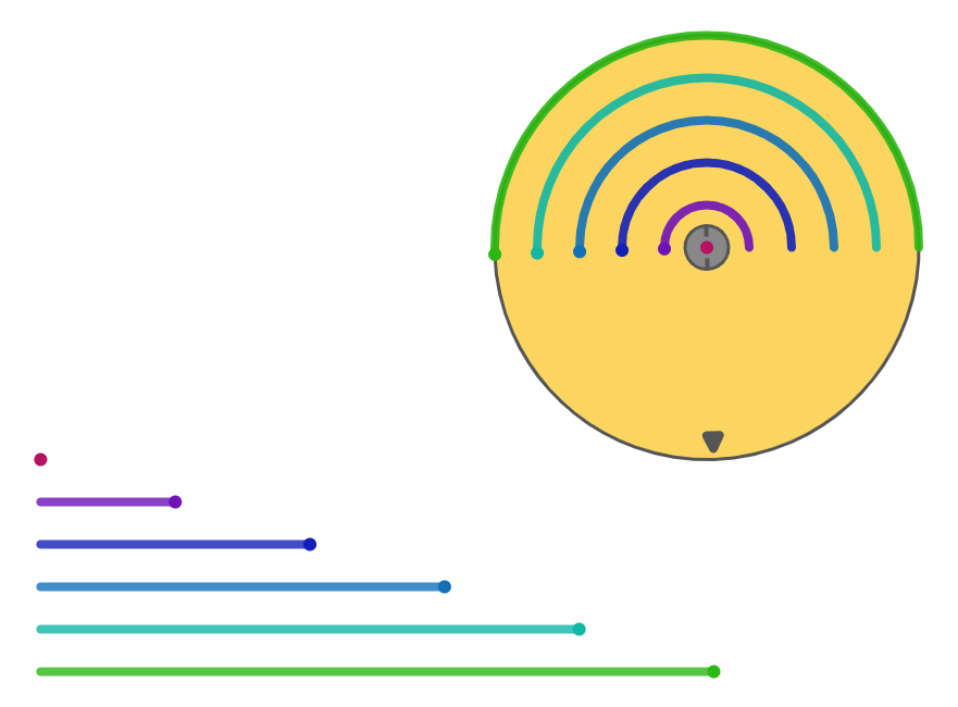
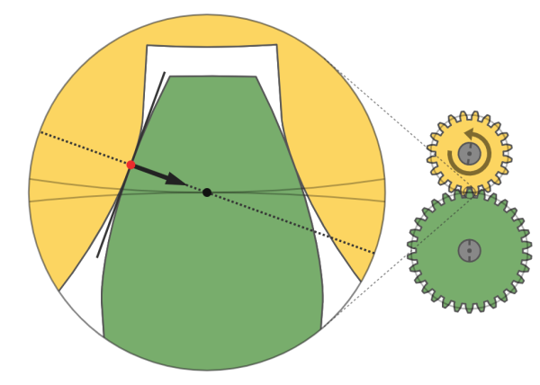
The post starts at the beginning – not “how to calculate a gear ratio” – but how does rotational motion work at all. The illustrations help give the reader an intuitive sense for how the rate of rotation is measured and what that measurement actually represents in the real world. From there [Bartosz] builds up to describing how two discs touching edge to edge transfer motion and the relationship of their size on that process. After explaining torque he has the fundamentals in place to describe why gears have teeth, and why they work at all.
Well written explanatory copy aside, the real joy in this post is the interactivity. Each concept is illustrated, and each illustration is interactive. Images are accompanied by a slider which lets you adjust what’s shown, either changing the speed of a rotating gear or advancing the motion of two teeth interlocking. We found that being able to move through time this way really helped form an intuitive understanding of the concepts being discussed. This feels like the dream of interactive multimedia textbooks come to life.