Ambient Lighting For Baby With The ESP8266

There are plenty of great reasons to have a child. Perhaps you find the idea of being harshly criticized by a tiny person very appealing, or maybe you enjoy somebody screaming nonsense at you while you’re trying to work on something. But for us, we think the best reason for procreation is getting another excuse to build stuff. It’ll be what, at least two years before a baby can solder or program a microcontroller? Somebody’s going to have to do it for them until then.

To try to help his baby daughter get on a better sleep schedule, [Amir Avni] decided to outfit her room with some “smart” lighting to establish when it’s time for her to wake up. Not only can he and his wife control the time the lights come on to “day” mode, but they can also change the colors. For example, they can switch over to a red glow at night. Despite some learning experience setbacks, the both the parents and the baby are very happy with the final product.

An ESP8266 controls a WS2812 LED strip to provide the adjustable lighting, and a DHT22 sensor was added to the mix to detect the temperature and humidity in the baby’s room. [Amir] used Blynk to quickly throw together a slick mobile application that allows for complete control of the brightness and color of light in the room, as well as provides a readout of the environmental data pulled from the DHT22.

But not everything went according to plan. [Amir] thought he could power the LED strip from the ESP8266 development board by soldering to the 5 V side of its AMS1117 voltage regulator. Which worked fine, until he turned on too many LEDs. Then it pulled too much current through a resistor connected to the regulator, and let all the magic smoke out. An important reminder of what can happen when we ask more of a circuit than what it was designed for.

We’ve covered many awesome projects that were born of a parental need, from feature packed baby monitors to devices seemingly designed to program nostalgia in the little one’s subconscious.

Illuminated Bread For A Cookie Cutter World

Just in case you thought your eyes were playing tricks on you, we’d like to confirm right from the start that what you are looking at is a loaf of bread with internal LED lighting. Why has this bread been internally lit? We can’t really say. But what we can do is pass on the fascinating process that took an unremarkable piece of stale bread and turned it into an exceptional piece of stale bread.

As demonstrated by [The Maker Monster], working with stale bread is basically like working with wood. Wood that you can dip in soup, granted, but wood nonetheless. The process of electrifying the loaf starts with cutting it down the length on a bandsaw, and then hollowing it out with a rotary tool. This creates a fairly translucent shell that’s basically just crust.

You’re probably wondering how you keep a bread-light from getting moldy, and thankfully [The Maker Monster] does address that issue. The bread shell is completely coated with shellac, which creates a hard protective layer that will not only prevent decay but should give it some added strength. In the video it looks like only one coat is applied, but if we had to guess, a few coats would be necessary to really seal it up. Coating it with epoxy wouldn’t be a terrible idea either.

While the shellac dries on the bread, he gets to work on the lighted base (bet you never imagined you’d read a sentence like that), which is really just a sanded piece of wood with a standard LED strip stuck too it. It’s very understated, but of course the glowing loaf really draws the eye anyway. All that’s left is to glue the bread down to the base, and proudly display your creation at your next dinner party.

We can’t say that an electric ciabatta is in the cards for Hackaday HQ; but we know that baking good bread is a science in itself, and turning the failed attempts into works of art does have a certain appeal to it.

Continue reading “Illuminated Bread For A Cookie Cutter World”

Supercapacitors In A Servo: The “Forever” Flashlight

The principle is well understood: use a motor in reverse and you get a generator. Using this bit of knowledge back in 2001 is what kick-started [Ted Yapo]’s Hackaday Prize entry. At the time, [Ted] was searching for a small flashlight for astronomy, but didn’t like dealing with dead batteries. He quickly cobbled together a makeshift solution out of some supercapacitors and a servo-as-a-generator, hacked for continuous rotation.

A testament to the supercapacitors, 17 years later it’s still going strong – leading [Ted] to document the project and also improve it. The original circuit was as simple as a servo, protection diode, some supercapacitors, and a LED with accompanying resistor; but now greater things are afoot.

A DC-DC boost converter enables constant power through the LED, regardless of the capacitor voltage. This is achieved by connecting the feedback pin of an MCP1624 switcher to an INA199 current-shunt monitor. The MCP1624 kicks in at 0.65V and stays active down to 0.35V. This is all possible due to the supercapacitors, which happily keep increasing current as voltage drops – all the way to 0.35V. Batteries are less ideal in this situation, as their internal resistance increases as voltage drops, as well as increasing with age.

When testing the new design, [Ted] found that the gears on his servos kept stripping when he was using them to charge capacitors. Though at first he attributed it to the fact that the gears were plastic, he realized that his original prototype from 2001 had been plastic as well. Eventually, he discovered the cause: modern supercapacitors are too good! The ones he’d been using in 2001 were significantly less advanced and had a much higher ESR, limiting the charging current. The only solution is to use metal gear servos

Want to read more about boost converter design? We have the pros and cons of microcontrollers for boost converters, or this neat Nixie driver for USB power.

Tiny $25 Spectrometer Aims To Identify Materials With Ease

Reflectance spectrometers work on a simple principle: different things reflect different wavelengths in different amounts, and because similar materials do this similarly, the measurements can be used as a kind of fingerprint or signature. By measuring how much of which wavelengths get absorbed or reflected by a thing and comparing to other signatures, it’s possible to identify what that thing is made of. This process depends heavily on how accurately measurements can be made, so the sensors are an important part.

[Kris Winer] aims to make this happen with the Compact, $25 Spectrometer entry for The 2018 Hackaday Prize. The project takes advantage of smaller and smarter spectral sensors to fit the essential bits onto a PCB that’s less than an inch square. If the sensors do the job as expected then that’s a big part of the functionality of a reflectance spectrometer contained in a PCB less than an inch square and under $25; definitely a feat we’re happy to see.

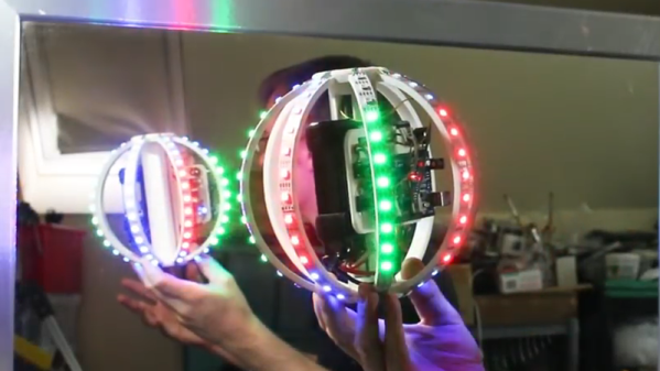
Atltvhead - wearable interactive TV

RCA TV Gets New Life As Interactive Atltvhead

TVs are usually something you sit and passively watch. Not so for [Nate Damen’s] interactive, wearable TV head project, aka Atltvhead. If you’re walking around Atlanta, Georgia and you see him walking around with a TV where his head should be, introduce yourself! Or sign into Twitch chat and take control of what’s being displayed on the LEDs which he’s attached to the screen. Besides being wearable technology, it’s also meant to be an interactive art piece.

For this, his third version, the TV is a 1960’s RCA Victor Portable Television. You can see some of the TVs he found for previous versions on his hackaday.io page. They’re all truly vintage. He gutted this latest one and attached WS2812 LED strips in a serpentine pattern inside the screen. The LEDs are controlled by his code and the FastLED library running on an ESP8266. Power comes from four NiMH AA-format batteries, giving him 5 V, which he regulates down to 3.3 V. His phone serves as a WiFi hotspot.

[Nate] limits the commands so that only positive things can be displayed, a heart for example. Or you can tweak what’s being displayed by changing the brightness or make the LEDs twinkle. Judging by the crowds we see him attracting in the first video below, we’d say his project was a huge success. In the second video, Nate does a code walkthrough and talks about some of his design decisions.

Continue reading “RCA TV Gets New Life As Interactive Atltvhead”

Watch The Honeycomb Clock Gently Track Time

We love clocks here at Hackaday, and so does [John Whittington]. Last year he created this hexagonal honey clock (or “Honock”) by combining some RGB LEDs with a laser-cut frame to create a smooth time display that uses color and placement to display time with a simple and attractive system.

The outer ring of twelve hexagons is essentially the hour hand, similar to analog clock faces: twelve is up, three is directly to the right, six is straight down, and nine is to the left. The inner ring represents ten minutes per hex. Each time the inner ring fills, the next hex (hour) on the outer ring lights up. The whole display is flooded with a minute-long rainbow at noon and midnight. Watch it in action in the video, embedded below.

Continue reading “Watch The Honeycomb Clock Gently Track Time”

Animated Bluetooth Bike Turn Signals

Tired of risking his life every time he had to signal a turn using his hands while riding his bicycle in rainy Vancouver, [Simon Wong] decided he needed something a bit higher tech. But rather than buy something off the shelf, he decided to make it into his first serious Arduino project. Given the final results and the laundry list of features, we’d say he really knocked this one out of the park. If this is him getting started, we’re very keen to see where he goes from here.

So what makes these turn signals so special? Well for one, he wanted to make it so nobody would try to steal his setup. He wanted the main signal to be easily removable so he could take it inside, and the controls to be so well-integrated into the bike that they wouldn’t be obvious. In the end he managed to stuff a battery pack, Arduino Nano, and an HC-05 module inside the handlebars; with just a switch protruding from the very end to hint that everything wasn’t stock.

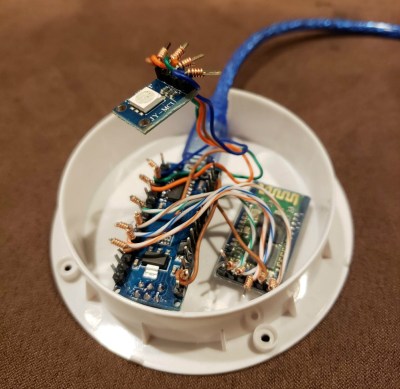
On the other side, a ATMEGA328P microcontroller along with another HC-05 drives two 8×8 LED matrices with MAX7219 controllers. Everything is powered by a 18650 lithium-ion battery with a 134N3P module to bring it up to 5 VDC. To make the device easily removable, as well as keep the elements out, all the hardware is enclosed in a commercial waterproof case. As a final touch, [Simon] added a Qi wireless charging receiver to the mix so he could just pull the signal off and drop it on a charging pad without needing to open it up.

It’s been some time since we’ve seen a bike turn signal build, so it’s nice to see one done with a bit more modern hardware. But the real question: will he be donning a lighted helmet for added safety?

Continue reading “Animated Bluetooth Bike Turn Signals”