The ESP32 was introduced a few years ago as an inexpensive way to outfit various microcontrollers with WiFi or Bluetooth. Since then it has been experimented with and developed on, thanks to its similarities to the ESP8266 and the ability to easily program it. Watching the development of this small chip has truly been fascinating as it continues to grow. Or, in this case, shrink.
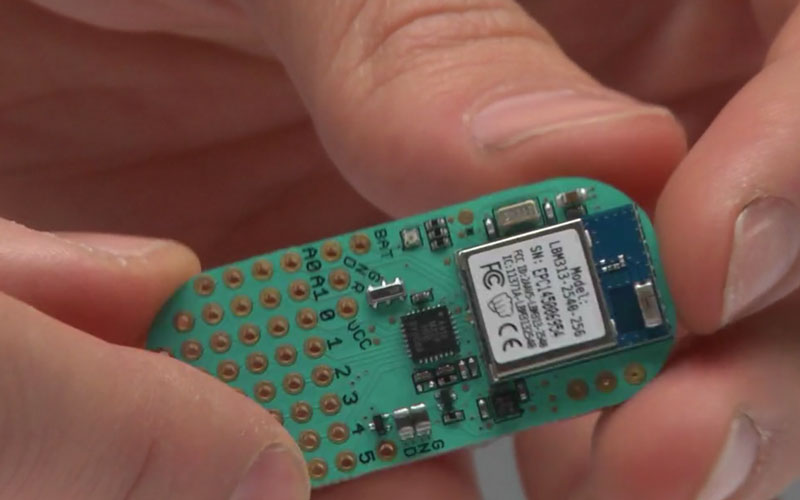
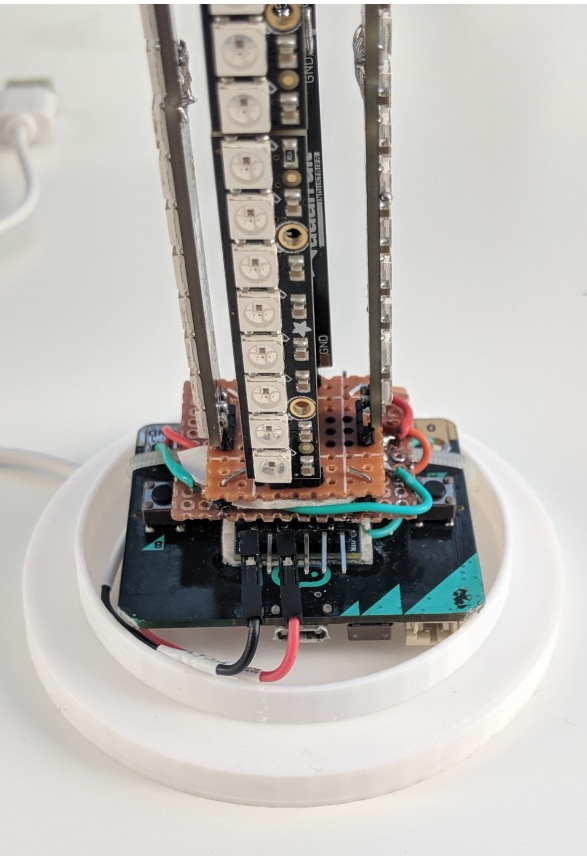
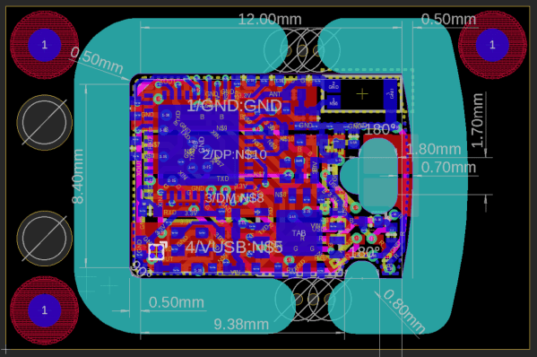
The latest development in the ESP32 world comes from [femtoduino] who, as the name suggests, makes very small things. This one is a complete ESP32 which fits inside a USB-A connector. The brains of the projects is the ESP32-D2WD which is a dual core chip with 2 Mb of memory, making it more than capable. In fact, a big part of this project was [femtoduino]’s modifications to MicroPython in order to allow it to run on this chipset. For that alone, it’s cool.
This project is impressive for both reasons, both the size and the addition to the MicroPython libraries. If you need something really really tiny, for whatever reason, you might want to look into picking up one of these. Be careful though, and be sure to get the latest version of the SDK.