ESP8266 Keeps Tabs On The Kid’s Tablets

Assuming you have a child and it’s no longer womb-bound, there’s a fairly high chance they’ve already had some experience with the glowing beauty that is the LCD display; babies of only a few months old are often given a tablet or smartphone to keep them occupied. But as the child gets to the age where they are capable of going outside or doing something more constructive, staring slack-jawed and wide-eyed at their tablet becomes a concern for many parents.

[Richard Garsthagen] is one such parent. He wanted a way to monitor and control how much time his children were using their iPad, so he came up with an automated system based on the ESP8266. Not only does it keep track of how long the tablet is being used, it even includes a reward system which allows the parent to add extra usage time for good behavior.

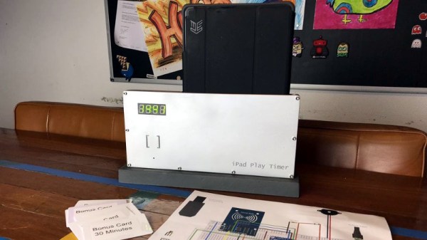
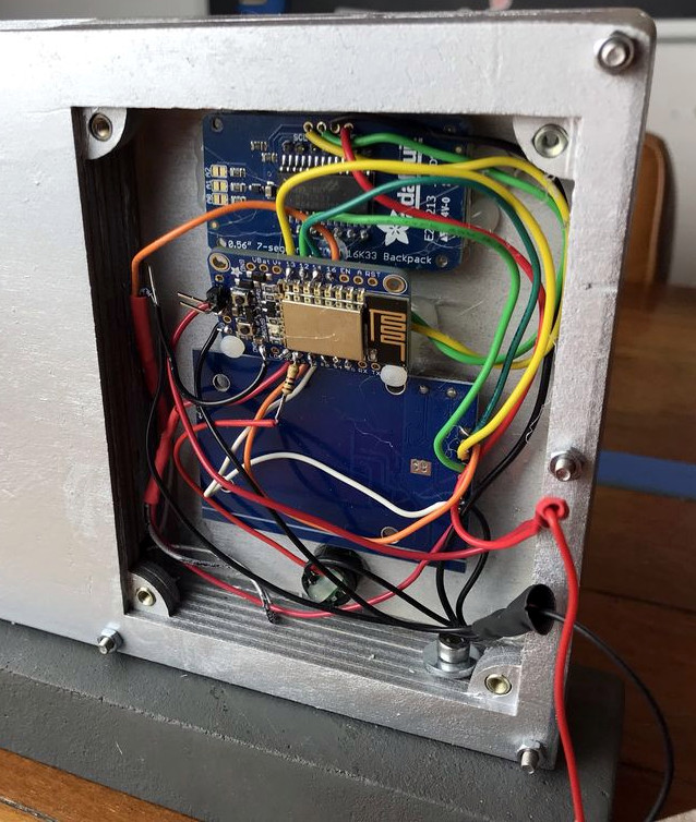
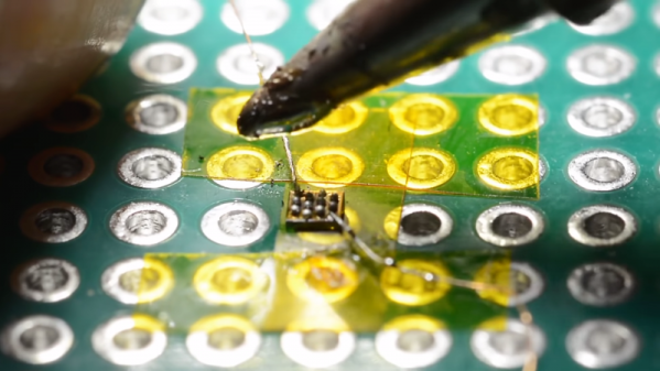
At the most basic level, the device is a sort of “holster” for the child’s tablet. When the tablet is placed in the slot, it presses a microswitch at the bottom of the cavity which stops the timer. When the switch is open, the LED display on the front of the device counts down, and the ESP8266 pushes notifications about remaining time to the child’s device via IFTTT.

Time can be added to the clock by way of RFID cards. The cards are given out as a reward for good behavior, completion of chores, etc. The child only needs to pass the card in front of the system to redeem its value. Once the card has been “spent”, the parent can reset it with their own special card.

It’s a very slick setup, making perfect use of the ESP8266. Reading the RFID cards, updating the timer, and using IFTTT’s API keeps the little board quite busy; [Richard] says it’s completely maxed out.

You might be wondering what happens when the clock reaches zero. Well, according to the video after the break…nothing. Once the time runs out, a notification simply pops up on the tablet telling them to put it away. Some might see this as a fault, but presumably it’s the part of the system where humans take over the parenting and give the ESP8266 a rest.

This isn’t the first time we’ve seen a microcontroller used to get the little hackers on schedule. At least (so far) none of them have gone full Black Mirror and started tracking when the kiddos are watching it.

Continue reading “ESP8266 Keeps Tabs On The Kid’s Tablets”

The Smaller, Tinier Arduino Platform

While many of the Arduino platforms are great tools for gaining easy access to microcontrollers, there are a few downsides. Price and availability may be the highest on the list, and for those reasons, some have chosen to deploy their own open-source Arduino-compatible boards.

The latest we’ve seen is the Franzininho, an Arduino Gemma-like board that’s based on the ATtiny85, a capable but tiny microcontroller by Atmel in a compact 8-pin configuration. This board has everything the Gemma has, including a built-in LED and breakout pins. One of the other perks of the Franzininho over the Gemma is that everything is based on through-hole components, making the assembly much easier than the surface mount components of the Gemma.

It’s worth noting that while these boards are open source, the Arduinos are as well. It’s equally possible to build your own 100% identical Arduino almost as easily. If you want more features, you can add your own by starting from one of these platforms and do whatever you want with it, like this semi-educational Atmel breakout board.

Thanks to [Clovis] for the tip!

The A To Z Of Building Your Own Keyboard

We’ve featured a number of people who’ve taken the plunge and created their own customized keyboard; at this point it’s safe to say that there’s enough information and source code out there that anyone who’s looking to build their own board won’t have much trouble figuring out how to do so. That being said, it’s nice to have a comprehensive at a process from start to finish. Why sift through forum posts and image galleries looking for crumbs if you don’t have to?

That’s precisely what makes this write-up by [Maarten Tromp] so interesting. He walks the reader through every step of the design and creation of his customized keyboard, from coming up with the rather unique layout to writing the firmware for its AVR microcontroller. It’s a long read, filled with plenty of tips and tricks from a multitude of disciplines.

After looking at other custom boards for inspiration, [Maarten] used OpenSCAD to create a 3D model of his proposed design, and had it printed at Shapeways. His electronics are based around an Atmel ATMega328P using vUSB, and Microchip MCP23017 I/O expanders to connect all the keys. He wrapped it all up by designing a PCB in gEDA PCB and having it sent off for production. As a testament to his attention to detail, everything mated up on the first try.

[Maarten] is happy with the final product, but mentions that in a future revision he would like to add RGB lighting and use a microcontroller that has native USB support. He’d also like to drop the I/O expanders and switch over to Charlieplexing for the key matrix.

From uncommon layouts to diminutive technicolor beauties, it seems there’s no end of custom keyboards in sight. We aren’t complaining.

PIC Powered PicoBat Picks Up Pulsed Power

In 2012, [Bruno] wanted to detect some bats. Detect bats? Some varieties of bat (primarily the descriptively named “microbats”) locate themselves and their prey in space using echolocation, the same way your first robot probably did. The bat emits chirps from their adorably tiny larynx the same way a human uses its vocal cords to produce sound. The bat then listens for an echo of that sound and can make inferences about the location of its presumed prey in the volume around it. Bat detectors are devices which can detect these ultrasonic sounds and shift them into a range that humans can hear. So how would you build such a device? [Bruno]’s PicoBat probably sets the record for component count and code simplicity.

With no domain expertise the most conspicuous way to build a bat detector is probably to combine the glut of high performance microcontrollers with a similarly high performing analog to digital converter. With a little signal processing knowledge you sample the sounds at their native frequency, run them through a Fast Fourier transform, and look for energy in the ultrasonic frequency range, maybe about 20 kHz to 100 kHz, according to Wikipedia. With more knowledge about signal interference it turns out there are a surprisingly large number of ways to build such a device, including some which are purely analog. (Seriously, check out the Wikipedia page for the myriad ways this can be done.)

[Bruno] did use a microcontroller to build his bat detector, but not in the way we’d have expected. Instead of using a beastly high performance A/D and a similarly burly microcontroller, the PicoBat has a relatively tame PIC12 and a standard ultrasonic transducer, as well as a piezo buzzer for output. Along with a power rail, that’s the entire circuit. The code he’s running is similarly spartan. It configures a pair of GPIOs and toggles them, with no other logic. That’s it.

So how does this work? The ultrasonic transducer is designed mechanically to only receive sounds in the desired frequency range. Being piezoelectric, when enough sound pressure is applied the stress causes a small voltage. That voltage is fed into the PIC not as a GPIO but as a clock input. So the CPU only executes an instruction when ultrasonic sound with enough intensity hits the transducer. And the GPIO toggling routine takes four clock cycles to execute, yielding a 1:4 clock divider. And when the GPIOs toggle they flip the potential across the buzzer, causing it to make human-audible sound. Brilliant!

Check out [Bruno]’s video demo after the break to get a sense for how the device works. You might be able to do this same trick with other components, but we’re willing to be that you won’t beat the parts count.

Continue reading “PIC Powered PicoBat Picks Up Pulsed Power”

No Caffeine, No Problem: A Hand-Soldered Chip-Scale Package

It’s said that the electronic devices we use on a daily basis, particularly cell phones, could be so much smaller than they are if only the humans they’re designed for weren’t so darn big and clumsy. That’s only part of the story — battery technology has a lot to do with overall device size — but it’s true that chips can be made a whole lot smaller than they are currently, and are starting to bump into the limit of being able to handle them without mechanical assistance.

Or perhaps not, if [mitxela]’s hand-soldering of a tiny ball-grid array chip is any guide. While soldering wires directly to a chip is certainly a practical skill and an impressive one at that, this at least dips its toe into the “just showing off” category. And we heartily endorse that. The chip is an ATtiny20 in a WLCSP (wafer-level chip-scale package) that’s a mere 1.5 mm by 1.4 mm. The underside of the chip has twelve tiny solder balls in a staggered 4×6 array with 0.4 mm pitch. [mitxela] tackled the job of soldering this chip to a 2.54-mm pitch breakout board using individual strands from #30 AWG stranded wire and a regular soldering iron, with a little Kapton tape to hold the chip down. Through the microscope, the iron tip looks enormous, and while we know the drop of solder on the tip was probably minuscule we still found ourselves mentally wiping it off as he worked his way across the array. In the end, all twelve connections were brought out to the protoboard, and the chip powers up successfully.

We’re used to seeing [mitxela] work at a much larger scale, like his servo-plucked music box or a portable Jacob’s Ladder. He’s been known to get small before though, too, like with these tiny blinkenlight earrings.

Continue reading “No Caffeine, No Problem: A Hand-Soldered Chip-Scale Package”

SiFive Releases Smaller, Lower Power RISC-V Cores

Today, SiFive has released two new cores designed for the lower end of computing. This adds to the company’s existing portfolio of microcontrollers and SoCs based on the Open RISC-V ISA. Over the last two years, SiFive has introduced a number of cores based on the RISC-V ISA, an Open Architecture ISA that gives anyone to design and develop a microcontroller or microprocessor platform. These two new cores fill out the low-power end of SiFive’s core portfolio.

The two new cores included in the announcement are the SiFive E20 and E21, both meant for low-power applications, and according to SiFive presentations, they’re along the lines of an ARM Cortex-M0+ and ARM Cortex-M4. This is a core — it’s not a chip yet — but since the introduction of SiFive’s first microcontrollers, many companies have jumped on the RISC-V bandwagon. Western Digital, for example, has committed to using the RISC-V architecture in SoCs and as controllers for hard drive, SSDs, and NASes.

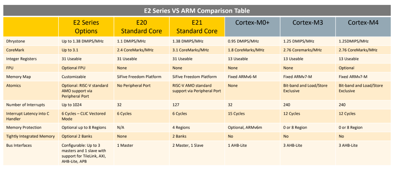
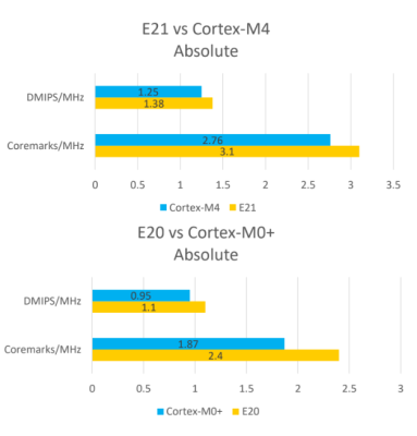
The first chip from SiFive was the HiFive 1, which was based on the SiFive E31 CPU. We got our hands on the HiFive 1 early last year, and it is a beast. With the standard complement of benchmarks, in terms of raw power, it’s approximately twice as fast as the Teensy 3.6, based on the Kinetis K66, a 180 MHz ARM Cortex-M4F. The SiFive E31 is about 1.5 times as fast as the Teensy 3.6 on a pure calculations per clock basis. This is remarkable because the Teensy 3.6 is our go-to standard for when you want to toggle pins really really fast with a cheap, readily available microcontroller platform.

But sometimes you don’t need the fastest or best microcontroller. To that end, SiFive is looking toward a lower-power microcontroller based on the RISC-V core. The new offerings are built on the E2 Core IP series, with two standard cores. The E21 core provides mainstream performance for microcontrollers, and the E20 core is the most power-efficient core offered by SiFive. In effect, the E21 core is a replacement for the ARM Cortex-M3 and Cortex-M4, while the E20 is a replacement for the ARM Cortex-M0+.

Just a few months ago, SiFive released a gigantic, multicore, Linux-capable processor called the HiFive Unleashed. With support for DDR4 and Gigabit Ethernet, this chip would be more at home in a desktop than an Internet of Things thing. The most popular engine ever produced isn’t a seven-liter turbo diesel, it’s whatever goes into a Honda econobox; likewise, many more low-power microcontrollers like the Cortex-M0 and -M3 are sold than the newer, more powerful, and more expensive chips. Even though it’s not as exciting as a new workstation CPU, the world needs microcontrollers, and the more Open, the better.

A Crash Course In Reliable Communication

It’s probably fair to say that anyone reading these words understands conceptually how physically connected devices communicate with each other. In the most basic configuration, one wire establishes a common ground as a shared reference point and then the “signal” is sent over a second wire. But what actually is a signal, how do the devices stay synchronized, and what happens when a dodgy link causes some data to go missing?

All of these questions, and more, are addressed by [Ben Eater] in his fascinating series on data transmission. He takes a very low-level approach to explaining the basics of communication, starting with the concept of non-return-to-zero encoding and working his way to a shared clock signal to make sure all of the devices in the network are in step. Most of us are familiar with the data and clock wires used in serial communications protocols like I2C, but rarely do you get to see such a clear and detailed explanation of how it all works.

He demonstrates the challenge of getting two independent devices to communicate, trying in vain to adjust the delays on the receiving and transmitting Arduinos to try to establish a reliable link at a leisurely five bits per second. But even at this digital snail’s pace, errors pop up within a few seconds. [Ben] goes on to show that the oscillators used in consumer electronics simply aren’t consistent enough between devices to stay synchronized for more than a few hundred bits. Until atomic clocks come standard on the Arduino, it’s just not an option.

[Ben] then explains the concept of a dedicated clock signal, and how it can be used to make sure the devices are in sync even if their local clocks drift around. As he shows, as long as the data signal and the clock signal are hitting at the same time, the actual timing doesn’t matter much. Even within the confines of this basic demo, some drift in the clock signal is observed, but it has no detrimental effect on communication.

In the next part of the series, [Ben] will tackle error correction techniques. Until then, you might want to check out the fantastic piece [Elliot Williams] put together on I2C.

[Thanks to George Graves for the tip.]

Continue reading “A Crash Course In Reliable Communication”