J1: A Small, Fast, CPU Core For FPGA

[James Bowman] of the Willow Garage published a paper on his J1 CPU core for field-programmable gate arrays. This was originally developed and used for the Ethernet cameras on the PR2 (you know, that incredibly expensive beer delivery system?) robot. It uses a 16-bit von Neumann architecture and lacks several processor features you’d expect a CPU to have such as interrupts, multiply and divide, a condition register, and a carry flag. None-the-less, its compact at just 200 lines of Verilog and it can run at 80 MHz. [James] compares the J1 to three different FPGA CPU Cores commonly used and discusses how the system is built in his 4-page paper that has the details you’re interested in but won’t take all day to dig through.

VGA Interfacing AVR Microcontrollers

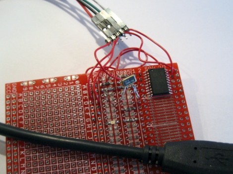
[Lucidscience] is back again, this time showing us how to push data to a VGA monitor from your AVR project.  It turns out that it is pretty simple, requiring only n open port and a few resistors and diodes. Well, it is that simple for the most basic version which gives you 56×60 pixels. Of course he couldn’t live with that and had to expand. Version 2 outputs 240×240 resolution and has additional sram and a double buffer making animations smoother and flicker free. As usual, the project is quite well documented with photos of the entire build process and schematics for you to build your own. A video of version 1 and version 2 are available after the break.

[via HackedGadgets]

Continue reading “VGA Interfacing AVR Microcontrollers”

SmartLCD Makes Video For Microcontrollers Easy

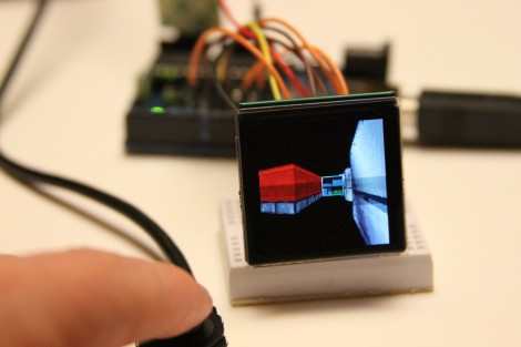
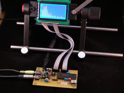
[Rossum] developed a host board that makes it easy to drive a TFT screen using an inexpensive microcontroller. He’s looked around at a bunch of LCD’s that are easy to get your hands on and decided that the iPod Nano 2G screens are the right balance of performance (176×132 TFT) and low cost ($1-$5). They’re not particularly difficult to talk to, but with 22 pins they’re a bit hardware hungry.

He takes us through the signal sniffing he used to figure out the communications process. From there he harness the power of an ARM Cortex M0 processor, which he’s worked with in the past, to drive the screen. His implementation results in a driver board called the SmartLCD that takes care of the screen’s parallel protocol, power, and backlight. From there it’s just four connections and you can use a small microcontroller like the Arduino seen above with ease. See what it can do after the break.

Continue reading “SmartLCD Makes Video For Microcontrollers Easy”

AVR Programming 04: Writing Code, Etc.

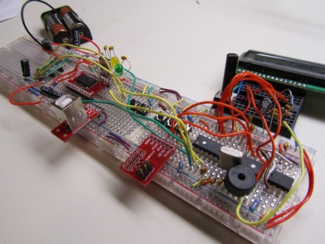
Welcome back to this fourth and final installment of the series. The first three parts should have been enough to get you off the ground, but a few more learning examples wouldn’t hurt. It’s also a good time to discuss some of the other things these little chips can do. Join me after the break to:

  • Expand the sample code, adding features to our simple program while I challenge you to write the code yourself.
  • Discuss AVR fuse bits, how to use them, and what to watch out for
  • Touch on some of the peripherals you’ll come across in these chips

As a grand flourish to the series, I’ve used the example hardware from this final part to build a bicycle tail light. Hopefully this will inspire you to create something much more clever.

Series roadmap:

Continue reading “AVR Programming 04: Writing Code, Etc.”

Build Your Own SOIC Progamming Clip

[Pyra] was looking for a way to reprogram some ATtiny13 microcontrollers in a SOIC package. He’s re-engineering some consumer electronics so adding an ISP header to the design isn’t an option. He had been soldering wires to the legs of every chip but this is quite tedious. What he needs is an adapter that can make physical contact with the legs just long enough to program new firmware. After looking around he discovered that a PCI socket can be used as a progamming clip (translated). It shares the same pitch as a standard SOIC package but is not wide enough for the chip. He cut out 4 rows of the socket and the section of motherboard it was soldered to. Then he made a cut down the middle of the plastic and bent the two sections apart. The image above illustrates this, but not shown are the eight wires that he later added to connect to the device.

We wonder if this can be adapted to program SOIC parts without removing them from a circuit board. That would be a handy tool for finishing up the LED lightbulb hack.

Dungeon Crawler Game For IM-ME (and Linux)

[Joby Taffey] takes the prize for the first completed homebrew game for the IM-ME. Over the last few weeks we’ve seen [Travis Goodspeed] working with sprite graphics, and [Emmanuel Roussel] developing game music for the pink pager. But [Joby] didn’t really use either of those.

[Travis’] sprites were using a framebuffer that fills up a lot of valuable RAM. [Joby] decided to draw the room screens (all of them have been stitched together for the image above) as a one-time background image to keep the memory free. From there, the screen is updated in 8×8 blocks based on cursor movement. He also decided not to add music as he feels the high-pitched piezo is not capable making sound without driving everyone crazy.

Source code is available and for those of you who don’t own this pretty handheld, the game can also be compiled in Linux.

Moving A Resistor For EvalBot Power When Programming

[Riley Porter] posted a picture of his EvalBot USB power hack. In the photo above we’ve put a box around D6 and D7. The development board ships with a 0 Ohm resistor in the D7 location, patching in power from the USB-B connector labeled USB DEVICE. He found that by moving that resistor to D6 he can power the board from the USB-B connector labeled ICDI.

That connector is the In-Circuit Debug Interface. TI sent us an EvalBot bundle so we pulled it out and tried it ourselves. If you plug in the ICDI it doesn’t power the board, and no USB devices register. Shorting the D6 pads changes this and the following USB device registers:

Bus 002 Device 062: ID 0403:bcd9 Future Technology Devices International, Ltd Stellaris Evaluation Board

So it looks like you need to have two USB connections or be using batteries in order to program the board via USB. The uC/OS-III hardcover book that ships with the EvalBot bundle includes board schematics. We took a look and were surprised to see that they show diodes installed on both pads. Rev A of the online schematics have been corrected, showing an omitted diode on D6 and the 0 Ohm resistor on D7. Images of both schematics are included after the break.

It would have been nice to see a selector switch installed here to give you a little more flexibility when prototyping.

Continue reading “Moving A Resistor For EvalBot Power When Programming”