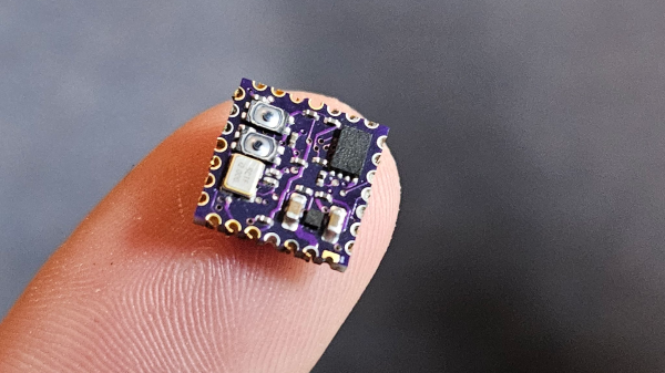
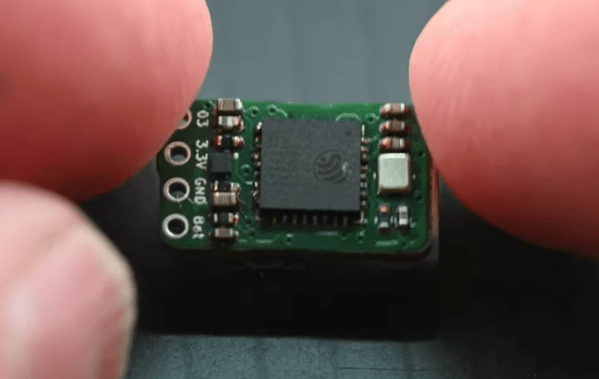
Wireless CNC Pendant Implemented With ESP-NOW

As a fervent fan of twiddly and twirly widgets and tactile buttons in a device’s user interface, [Steve M Potter] created a remote control (pendant) for his CNC machine, which he explains in a recent video that’s also linked down below. In addition to all the tactile goodness, what is perhaps most interesting about this controller is that it uses Espressif’s ESP-NOW protocol. This still uses the same 2.4 GHz as WiFi would, but uses a system more akin to the pairing of a wireless mouse or keyboard.

Advantages of ESP-NOW include the lower power usage, longer range, no requirement for a router and WiFi SSID & password. As far as latency goes, [Steve] measured a round-trip latency of 2.4 ms, which is fast enough for this purpose. Since it does control a potentially dangerous machine, all transmissions are acknowledged and re-transmitted at higher power if needed.

The lower power usage means that the pendant will last a lot longer on a single charge from the 18650 Li-ion cell, while ESP-NOW’s fixed address pairing saves time when turning the pendant on. Meanwhile, on the CNC side, another ESP32 acts as the receiving end for commands, although theoretically an ESP8266 could be used as well, if size or power was a concern there.

As for the transparent enclosure? It’s to make it easier to show it off to interested folk, apparently.

Continue reading “Wireless CNC Pendant Implemented With ESP-NOW”

New Part Day: ESP32-P4 Espressif RISC-V Powerhouse

It seems every day there’s a new microcontroller announcement for which the manufacturer is keen to secure your eyeballs. Today it’s the turn of Espressif, whose new part is the ESP32-P4, which despite being another confusingly named ESP32, is a high-performance addition to their RISC-V line-up.

On board are dual-core 400 MHz and a single-core low power 40 MHz RISC-V processors, and an impressive array of hardware peripherals including display and camera interfaces and a hardware JPEG codec alongside the ones you’d expect from an ESP32 part. It’s got a whopping 768 KB of on-chip SRAM as well as 8 K of very fast cache RAM for intensive operations.

So after the blurb, what’s in it for us? It’s inevitable that the RISC-V parts will over time displace the Tensilica parts over time, so we’ll be seeing more on this processor in upcoming Hackaday projects. We expect in particular for this one to be seized upon by badge developers, who are intent on pushing extra functionality out of their parts.So we look forward to seeing the inevitable modules with this chip on board, and putting them through their paces.

Thanks [Renze] for the tip.

A small brown PCB with various components on it. There is a headphone cable and DC barrel connector cable coming out of it.

Put Your Serial Port On The Web

Today, everything from your computer to your dryer has wireless communications built in, but devices weren’t always so unencumbered by wires. What to do when you have a legacy serial device, but no serial port on the computer you want to connect? [vahidyou] designed a wireless serial dongle to solve this conundrum.

Faced with a CNC that took instructions over serial port, and not wanting to deal with the cabling involved in a serial to USB adapter, [vahidyou] turned to an ESP8266 to let his computer and device talk wirelessly. The hand-made PCB connects via a 3.5 mm headphone jack to DB9 adapter which he describes in another article. While [vahidyou] did write a small Windows program for managing the device, it is probably easier to simply access it in a web browser from any device you have handy.

Want to see another wireless serial port application? This Palm Portable Keyboard Bluetooth dongle will let you type in comfort on the go, or you can use a PiModem to get your retrocomputer online!

PCB Gets Weighty Assignment

[Curious Scientist] tried building an integrated strain gauge on a PCB, but ran into problems. Mainly, the low resistance of the traces didn’t show enough change under strain to measure easily. Even placing a proper strain gauge on the PCB had limitations. His new design uses a bridge design to make the change in the gauges usefully large. You can see a video of the project below.

Bridging strain gauges isn’t a new idea. However, the novelty of this design is that the PCB has cantilever beams that facilitate the weighing. Standoffs mount a plate to the beams so that weight on the plate cause deformation on the beam that the strain gauges can measure.

Continue reading “PCB Gets Weighty Assignment”

The macropad PCB panel next to an assembled macropad

A Fun Low-Cost Start For Your Macropad Hobby

If you were ever looking for a small relaxing evening project that you could then use day-to-day, you gotta consider the Pico Hat Pad kit by [Natalie the Nerd]. It fits squarely within the Pi Pico form-factor, giving you two buttons, one rotary encoder and two individually addressable LEDs to play with. Initially, this macropad was intended as an under-$20 device that’s also a soldering practice kit, and [Natalie] has knocked it out of the park.

You build this macropad out of a stack of three PCBs — the middle one connecting the Pi Pico heart to the buttons, encoders and LEDs, and the remaining ones adding structural support and protection. All the PCBs fit together into a neat tab-connected panel — ready to be thrown into your favorite PCB service’s shopping cart. Under the hood, this macropad uses KMK, a CircuitPython-based keyboard firmware, with the configuration open-source. In fact everything is open-source, just the way we like it.

If you find yourself with an unexpected affinity for macropads after assembling this one, don’t panic. It’s quite a common side-effect. Fortunately, there are cures, and it’s no longer inevitable that you’ll go bananas about it. That said, if you’re fighting the urges to go bigger, you can try a different hand-wireable Pico-based macropad with three more keys. Come to find that one not enough? Here’s a 2×4 3D printable one.

Now, if you eventually find yourself reading every single Keebin’ With Kristina episode as soon as it comes out, you might be too far gone, and we’ll soon find you spending hundreds of dollars building tiny OLED screens into individual keys — in which case, make sure you document it and share it with us!

Continue reading “A Fun Low-Cost Start For Your Macropad Hobby”

Showing a board with a Pi Pico plugged into it, a USB-A socket marked "USB host", and a character display that says "PASSED" referring to the board being the brains of a testing jig.

USB Host On RP2040 – With PIO

Folks from [Adafruit] are showing off a neat hack – USB host on RP2040, using the now-famous PIO peripheral. [Adafruit] builds a lot of RP2040 boards, and naturally, you gotta test them before you ship them to customers. They’ve been using very specific Teensies for that, and at some point, those became unobtainium. Based on the work of [sekigon-gonnoc] and with help of [Thach], they’ve made their TinyUSB library support bitbanging of USB over PIO, and successfully ported their test jig firmware to it!

The base Pico-PIO-USB repo by [sekigon-gonnoc] shows a pretty impressive state of affairs – with low-speed and full-speed USB host and full-speed USB device modes supported, and quite a few examples to get you started. [Adafruit]’s work integrates this code into their TinyUSB stack, specifically focusing on MST (mass storage) features – as this is what you need to program a RP2040. Of course, they also provide a mass storage example to boot!

Test jigs are pretty important to have when making multiple pieces of a board, and with RP2040 supporting more and more interfaces thanks to PIO, it sounds like the perfect chip for your next production testing-intended PCB. With the jig brains taken care of, you’ll want to look into building no less important mechanical part, and we’ve covered quite a few ways to sort that out – here’s an OpenSCAD script that generates lasercutting files out of KiCad boards, or a jig built out of scrap copperclad FR4, and a pretty extensive tutorial on making your own lasercuttable jigs, to boot.

Continue reading “USB Host On RP2040 – With PIO”

Turning A Microchip MPLAB Snap Into A UDPI AVR Programmer

The Unified Program and Debug Interface (UPDI) is Microchip’s proprietary interface for programming and on-chip debugging, and has become the standard on AVR MCUs after Microchip’s purchase of Atmel. Being a proprietary interface means that even entry-level programmers like the Atmel-ICE are rather expensive at over $100. That’s when for [Scott W Harden] the question arose of whether the much cheaper MPLAB Snap board (~$34) could be used as well for AVR UDPI purposes.

The stages of grief that [Scott] went through before he had it working involved among others the updating of the MPLAB Snap board firmware, getting yelled at by the Microchip Studio IDE when attempting to use the Snap for AVR MCU programming, and ultimately fixing the board following the relevant Microchip Engineering Technical Note (ETN #36) that specifies the removal of a 4.7 kΩ pull-down resistor (R48) on the Snap board. This allows the UDPI line to be pulled high by the MCU.

As the ETN notes, an external pull-up may also be used to override the pull-down, which would leave the ICSP functionality of of the Snap intact. As [Scott] mentions in his conclusion, it feels as if UDPI AVR support with the Snap is really an afterthought for Microchip. Meanwhile there are also more DIY solutions as [Scott] adds, which are useful for just flashing the MCU. An example is with a USB-TTL serial adapter and pymcuprog.

The problem with DIY solutions like jtag2updi, ftdi2updi, and their kin is the effort required to assemble them, and the uncertainty of long-term support as the UPDI ecosystem keeps evolving with new devices and new features. The MPLAB Snap with resistor mod may be just that middle ground between an Atmel-ICE and reverse-engineered OSS projects.

(Featured image: MPLAB Snap resistor mod illustrated, from Microchip ETN #36)