When you see a project with a digital display these days, you’ll be forgiven for assuming that there’s some kind of microcontroller behind the scenes. And while that’s often the easiest way to get a project from idea to completion, it’s rarely the most interesting way.
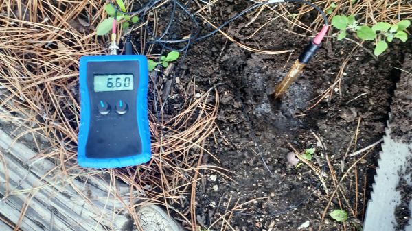
This digital pH meter is a great example of that “no-code” design philosophy. According to [chris], the main use for this meter will be to measure soil pH in his garden, and the reason for eschewing a microcontroller was more or less for the challenge. And quite a challenge it was. Understanding the concept of pH isn’t always easy, and many a budding chemist has fallen victim to its perils. Actually measuring pH isn’t much easier, with the need to account for a lot of variables while measuring small voltages. Adding to the challenge was the fact that pretty much every skill on display here — from using KiCad to SMD soldering — was the first time [chris] had tackled them.
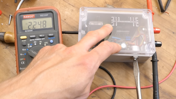
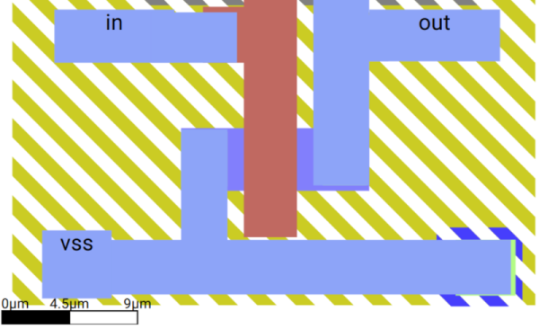
To amplify the voltage from the off-the-shelf pH probe, [chris] chose an LMV358A, a high-impedance FET-input version of the venerable LM358 op-amp, so as not to load down the probe. A negative temperature coefficient (NTC) resistor in the feedback path provides temperature compensation. He also designed a split power supply to provide positive and negative rails from a single 9-volt battery. The 3.5-digit LCD display is driven by an ICL7106 integrated A/D converter and BCD driver chip. Everything went into a nice-looking plastic enclosure that’s very suitable for a portable instrument.
As of this writing, the Op-Amp Challenge has officially wrapped, and there’s a slew of last-minute entries we need to go through. Check out the competition and stay tuned to find out who the judges pick for op-amp design glory!