
[Oliver Pett] loves creating automata; pieces of art whose physicality and motion come together to deliver something unique. [Oliver] also has a mission, and that mission is to complete the most complex automata he has ever attempted: The Archer. This automaton is a fully articulated figure designed to draw arrows from a quiver, nock them in a bow, draw back, and fire — all with recognizable technique and believable motions. Shoot for the moon, we say!
He’s documenting the process of creating The Archer in a series of videos, the latest of which dives deep into just how intricate and complex of a challenge it truly is as he designs the intricate cams required.
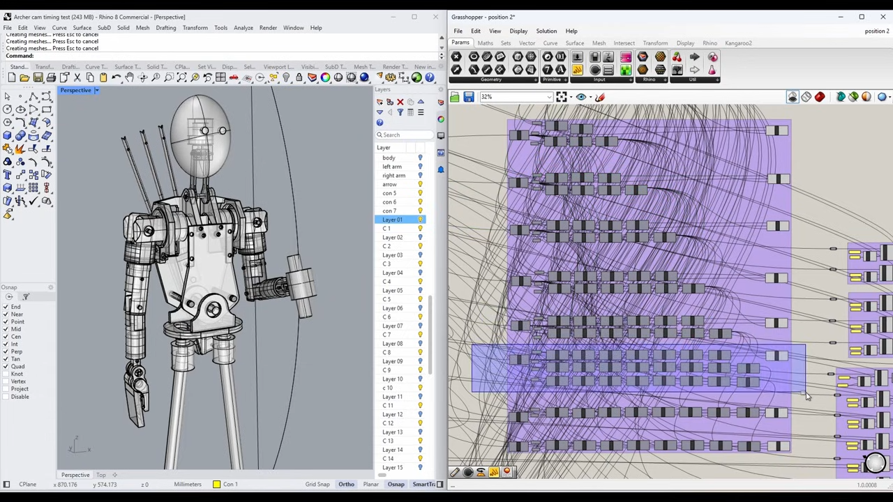
[Oliver] turned to modern CAD software and after making a digital twin of The Archer he’s been using it to mathematically generate the cam paths required to create the desired movements and transitions, instead of relying on trial and error. This also lets him identify potential collisions or other errors before any metal is cut. The cams are aluminum, so the fewer false starts and dead ends, the better!
Not only is The Archer itself a beautiful piece of work-in-progress, seeing an automaton’s movements planned out in this way is a pretty interesting way to tackle the problem. We can’t wait to see the final result.
Thanks [Stephen] for the tip!


