With the wide array of digital entertainment that’s available to young students, it can be difficult for educators to capture their imagination. In decades past, a “volcano” made with baking soda and vinegar would’ve been enough to put a class of 5th graders on the edge of their seats, but those projects don’t pack quite the same punch on students who may have prefaced their school day with a battle royale match. Today’s educators are tasked with inspiring kids who already have the world at their fingertips.
 Hoping to rise to that challenge with her entry into the 2019 Hackaday Prize, [Misty Lackie] is putting together a kit which would allow elementary and middle school students to build their very own fighting robots. Thanks to the use of modular components, younger students don’t have to get bogged down with soldering or the intricacies of how all the hardware actually works. On the other hand, older kids will be able to extend the basic platform without having to start from scratch.
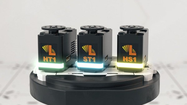
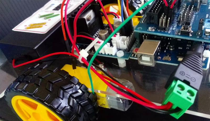
The electronics for the bot consist primarily of an Arduino Uno with Sensor Shield, a dual H-bridge motor controller, and a wireless receiver for a PS2 controller. This allows the students to control the bot’s dual drive motors with an input scheme that’s likely very familiar to them already. By mapping the controller’s face buttons to digital pins on the Arduino, additional functions such as the spinner seen in the bot after the break, easily be activated.
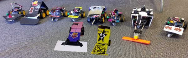
[Misty] has already done some test runs with an early version of the kit, and so far its been a huge success. Students were free to design their own bodies and add-ons for the remote controlled platform, and it’s fascinating to see how unique the final results turned out to be. We’ve seen in the past how excited students can be when tasked with customizing their own robots, so any entry into that field is a positive development in our book.
Continue reading “Bringing Battle Bots Into The Modern Classroom”