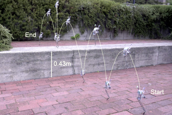
Most readers will be familiar with the work of the Dutch artist Theo Jansen, whose Strandbeest wind-powered mechanical walking sculptures prowl the beaches of the Netherlands. The Jansen linkage provides a method of making machines with a curious but efficient walking gait from a rotational input, and has been enthusiastically copied on everything from desktop toys to bicycles.
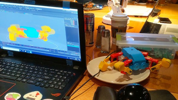
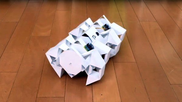
One might think that a Jansen linkage would be beyond some materials, and you might be surprised to see a paper one. Step forward [Luis Craft] then, with a paper walking Strandbeest. Designed in Blender, cut on a desktop CNC paper cutter, and driven by a pair of small robots linked to an Arduino and controlled by a Bluetooth link, it has four sets of legs and can push around desktop items. We wouldn’t have thought it possible, but there it is.
He claims that it’s an origami Strandbeest, but we’re not so sure. We’re not papercraft experts here at Hackaday, but when we put on our pedantic hat, we insist that origami must be made of folded paper in the Japanese style rather than the cut-and-glue used here. This doesn’t detract from the quality of the work though, as you can see in the video below.
We think this is the first paper Strandbeest we’ve seen, but we’ve brought you countless others over the years. Here’s [Jansen]’s latest, wave-like take on the idea.
Continue reading “Paper Strandbeest Is Strong Enough To Walk”