While autonomous robots have been the subject of some projects in the past, this particular project takes a swing at building a robot that can teach children about controls and robotics.
The idea is to mimic a space mission on the dark side of the moon, where radio contact is nearly impossible. The students learn to program and debug embedded devices and sensors, even before some of them have learned the alphabet!
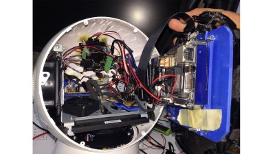
The material for the challenge allows the microcontroller to be programmed in a simple Arduino program (Blink) as well as lower level languages like C++ or Java. The main hardware consists of an Arduino Uno R3-based rover controlled over WiFi by an ESP8266. The sensor data from the robot is gathered from an ultrasound distance sensor an a camera, as well as a SIM7000E GSM+GPS. Commands are polled from a server, sent via a web page and REST interface.
The rover responds to commands for directions, takes pictures, and scans its distance remotely. Some custom libraries are written for the serial communication and camera to account for spotty communication. The latest challenge expansion is a probe that pays attention to battery life and power consumption, challenging students to account for power usage during the robot’s lifetime.
Since the project’s conception, the rovers have already been used in schools, and we’re excited to see a new approach for younger students to learn controls and programming.