It wouldn’t be much of a stretch to assume that anyone reading Hackaday regularly has at least progressed to the point where they can connect an LED to a microcontroller and get it to blink without setting anything on fire. We won’t even chastise you for not doing it with a 555 timer. It’s also not a stretch to say if you can successfully put together the “Hello World” of modern electronics on a breadboard, you’re well on the way to adding a few more LEDs, some sensors, and a couple buttons to that microcontroller and producing something that might come dangerously close to a useful gadget. Hardware hacking sneaks up on you like that.
Here’s where it gets tricky: how many of us are still stuck at that point? Don’t be shy, there’s no shame in it. A large chunk of the “completed” projects that grace these pages are still on breadboards, and if we had to pass on every project that still had a full-on development board like the Arduino or Wemos D1 at its heart…well, let’s just say it wouldn’t be pretty.
Of course, if you’re just building something as a personal project, there’s often little advantage to having a PCB spun up or building a custom enclosure. But what happens when you want to build more than one? If you’ve got an idea worth putting into production, you’ve got to approach the problem with a bit more finesse. Especially if you’re looking to turn a profit on the venture.
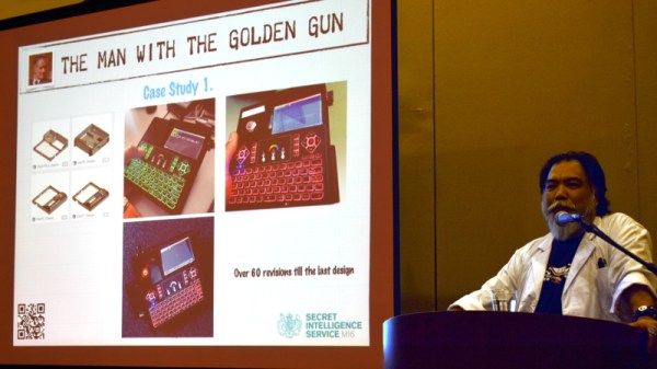
At the recent WOPR Summit in Atlantic City, there were a pair of presentations which dealt specifically with taking your hardware designs to the next level. Russell Handorf and Mike Kershaw hosted an epic four hour workshop called Strategies for your Projects: Concept to Prototype and El Kentaro gave a fascinating talk about his design process called Being Q: Designing Hacking Gadgets which together tackled both the practical and somewhat more philosophical aspects of building hardware for an audience larger than just yourself.
If you keep up with the field of web development, you may have heard of WebAssembly. A relatively new kid on the block, it was announced in 2015, and managed to garner standardised support from all major browsers by 2017 – an impressive feat. However, it’s only more recently that the developer community has started to catch up with adoption and support.
So, what is it? What use case is so compelling that causes such quick browser adoption? This post aims to explain the need for WebAssembly, a conceptual overview of the technical side, as well as a small hands-on example for context.
Ink! No matter the printer you’ve got, whether it be inkjet, laser or otherwise, it’s the consumables that will send you broke. At times, the cost of Hewlett-Packard black ink has exceeded the price per volume of human blood, and shareholders around the world have rejoiced.
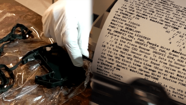
As a retrocomputing reprobate, I have a personal dilection for printers of the vintage persuasion. My previous dalliances have involved fully fledged office copiers, but lately I’ve found myself tinkering with dot matrixes of a 1980s vintage. These workhorses are now reaching middle age, and as you’d expect, their ribbons are a little worse for wear after all this time.
Replacements are cheap enough for the most common printers, but shipping takes weeks and hackers are an impatient bunch. Plus, if you’ve got one of the more obscure models, it’s unlikely you’ll find a fresh cart just sitting on the shelf. It was these factors that spurred my good friend [Cosmos2000] and I into action.
This is the 2019 Hackaday Prize, the worldwide hardware design contest focused on product development. We know you can build a working prototype, and we still want to see you do that. But a great idea should have reach beyond your own workshop. This year’s Hackaday Prize is about taking your product across the finish line, from concept to design for manufacture.
Prizes to Jump Start Your Product
$125,000 and a Supplyframe DesignLab Residency await the Best Product winner. There are five focus categories this year, with the winner of each receiving a $10,000 prize. And to help encourage those early beginnings, we have another $10,000 in seed funding set aside which means up to $500 for each of the top 20 entries who get in and gather those “likes” before June first.
There are a few areas of focus you should have in mind as you work on your products. These are Concept, Design, Production, Benchmark, and Communication. All entries are eligible to receive prizes related to these, and in addition to the $50,000 we mentioned above for the winner in each area, we have another $3,000 for each set aside to recognize an honorable mention.
Something amazing happened thirty years ago. A core of very motivated hackers took on the mantle of design, software, and even business skill, to build the computers that thrust us into a new information age. As these machines matured, a wave of software engineers picked up that torch, themselves embracing product and design thinking to accelerate the startup craze to new levels, again changing the world.
Ask yourself where we are right now. What are the hot new startups? The buzz now is all about billion dollar valuation but where is the substance? What we really need are the scrappy hackers who have a flag to plant to change the world. We’ve mistakenly been waiting for software companies to use their special sauce to lead a hardware renaissance, but instead it feels like we’re solving more and more trivial problems — where are the world-changers?
This is the hunger behind the 2019 Hackaday Prize. Three decades later, it is time for Hardware Engineers to be recognized as Innovators and leaders again. This is the call for the hardware community to come together, share knowledge, acquire new skills, and embark on a journey that uses the technological raw materials at our fingertips to invent the solutions that really matter. Make the idea and the execution happen now, and that enormous valuation will follow. Now is the time to change the world, you are the hackers who will do it, and this time around hardware will be leading the charge.
Improvisation, Mentorship, and Your Ability to Do Everything
We know you can build a working prototype of just about anything. But just like the creators of the Commodore, the Sinclair, Amiga, Apple, and Atari, you need to be more than a hardware designer. You need to know your users like you know yourself. You need an eye for industrial design — each of the machines mentioned above are iconic by how they look and not just by how they work. People behind these products knew what they were up against, and chose to make them stand-out designs in terms of performance, price, and how they fit into our lives.
You don’t have every skill necessary to make a great leap forward in every one of these areas — nobody does. But with the right community around you, you will learn some of them and find collaborators for the rest. Throughout the 2019 Hackaday Prize we’ll be pushing everyone to step past where you think your skills end, to learn what makes a product great, what makes it loved by the end user, and what makes it feasible to follow through to the end of the rainbow.
Get in early and take part in Prize demo days. Get matched up with world-class mentors and work with them in a masterclass situation from which everyone can learn. Show off your work and you’ll attract good ideas and good people. This is the Homebrew Computer Club of the new millennium. You’re going to find inspiration (and become the inspiration!) from everyone in the club. You’re going to riff on the breakthroughs of others, and together we’re all going to lead that Hardware Renaissance.
The 2019 Geneva International Motor Show has a number of “concept” vehicles. These are vehicles that usually include some cool feature that isn’t really practical — at least today. For example, in the past, concept cars have had adjustable color interior lighting, plug-in hybrid engines, and power windows — all things that would eventually become commonly available. However, today’s advances in computer-generated graphics have meant you can show things you can’t begin to build. Case in point: Goodyear has a video touting the Aero — a solid car tire that doubles as a propeller for your garden variety flying car.
To us, the thing looks more like a science fiction movie trailer than anything remotely practical. Four relatively small wheels with no central hub can flip and provide enough lift to propel a sizeable vehicle skyward. Even more interesting, is to transition modes from ground to flight, the vehicle balances on two wheels while using only two as propellers to generate lift.
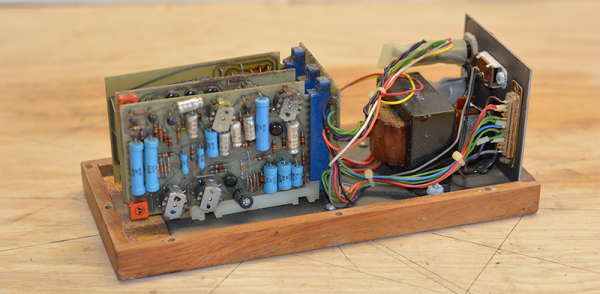
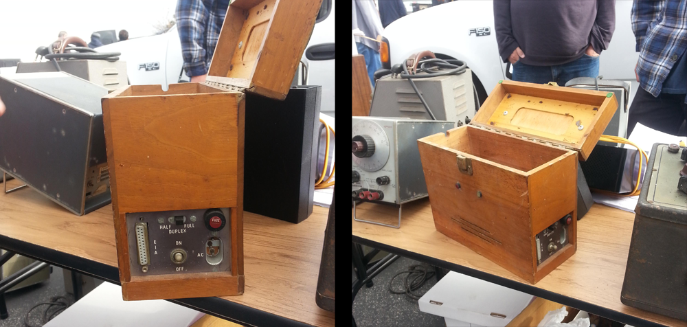
A few years ago, I was out at the W6TRW swap meet at the parking lot of Northrop Grumman in Redondo Beach, California. Tucked away between TVs shaped like polar bears and an infinite variety of cell phone chargers and wall warts was a small wooden box. There was a latch, a wooden handle, and on the side a DB-25 port. There was a switch for half duplex and full duplex. I knew what this was. This was a modem. A wooden modem. Specifically, a Livermore Data Systems acoustically coupled modem from 1965 or thereabouts.
The Livermore Data Systems Modem, where I found it. It cost me $20
The probability of knowing what an acoustically coupled modem looks like is inversely proportional to knowing what Fortnite is, so for anyone reading this who has no idea what I’m talking about, I’ll spell it out. Before there was WiFi and Ethernet and cable modems and fiber everywhere, you connected to the Internet and BBSes via phone lines. A modem turns digital data, in this case a serial connection, into analog data or sound. Oh yeah, we had phone lines, too. The phone lines and the phones in your house were owned by AT&T. Yes, you rented a phone from the phone company.
90s kids might remember plugging in a US Robotics modem into your computer, then plugging an RJ-11 jack into the modem. When this wooden modem was built, that would have been illegal. Starting with the communications act of 1934, it was illegal to attach anything to the phone in your house. This changed in 1956 with Hush-A-Phone Corp v. United States, which ruled you could mechanically attach something to a phone’s headset. (In Hush-A-Phone’s case, it was a small box that fit over a candlestick phone to give you more privacy.)
The right to attach something to AT&T’s equipment changed again in 1968 with Carterphone decision that allowed anyone to connect something electronically to AT&T’s network. This opened the door for plugging an RJ-11 phone jack directly into your computer, but it wasn’t until 1978 that the tariffs, specifications, and certifications were worked out. The acoustically coupled modem was the solution to sending data through the phone lines from 1956 until 1978. It was a hack of the legal system.
This leaves an ancient modem like the one sitting on my desk in an odd position in history. It was designed, marketed and sold before the Carterphone decision, and thus could not connect directly to AT&T’s network. It was engineered before many of the integrated chips we take for granted were rendered in silicon. The first version of this modem was introduced only a year or so after the Bell 103 modem, the first commercially available modem, and is an excellent example of what can be done with thirteen or so transistors. It’s time for the teardown, so let’s dig in.
We humans are good at a lot of things, but making holes in the ground has to be among our greatest achievements. We’ve gone from grubbing roots with a stick to feeding billions with immense plows pulled by powerful tractors, and from carving simple roads across the land to drilling tunnels under the English Channel. Everywhere we go, we move dirt and rock out of the way, remodeling the planet to suit our needs.
Other worlds are subject to our propensity for digging holes too, and in the 50-odd years that we’ve been visiting or sending robots as our proxies, we’ve made our marks on quite a few celestial bodies. So far, all our digging has been in the name of science, either to explore the physical and chemical properties of these far-flung worlds in situ, or to actually package up a little bit of the heavens for analysis back home. One day we’ll no doubt be digging for different reasons, but until then, here’s a look at the holes we’ve dug and how we dug them.