Is the second cheapest tool you can find any better than the cheapest one?
Readers with long memories will recall there was a time when I amused myself by tacking inexpensive tools or electronic devices to my various orders from the Chinese electronic Aladdin’s Cave. Often these inexpensive purchases proved to be as disastrous or ineffective as you might expect, but sometimes they show unexpected promise, true diamonds in the rough. It’s been a while and life has intervened over the last year, but it’s time to resume this harmless diversion.
Memories Of An Explosive Conclusion
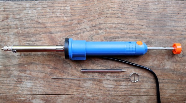
A particularly memorable review came in April 2018, when I bought a five pound ($6.30) desoldering iron. I described it then as an “unholy lovechild of a cheap solder sucker and an even cheaper soldering iron“, and while that was an accurate portrayal it also showed promise as a useful tool that would fill a niche in my requirements. Desoldering is always slightly annoying, and a heated desolder pump genuinely does make a difference. Unfortunately for me, the cheap desoldering tool was not a product I’d recommend that anyone try for themselves. A combination of questionable electrical safety and a propensity to explosively deconstruct itself meant it has languished unused in my big box of cheap junk, and I’m still without a decent desoldering solution. It is time to buy something better, and in the rich tradition of reviewing inexpensive stuff I decided to pick up the next cheapest desoldering iron I could find. Eight pounds ($10) secured me a Shi Yi Tool Sy365-8, and I set to on this review. Continue reading “Review: Shi Yi Tool Sy365-8 Desoldering Iron, Second Cheapest You Can Find”