From Leatherman multitools to oscilloscopes with built-in signal generators and protocol analyzers, there seems no end to tools with multiple personalities. Everybody loves multitaskers because they make it feel like you’re getting more bang for your buck, and in most cases that’s true. But a jack of all trades is seldom master of any, and there are times when even the humble multimeter isn’t the best tool for the job.
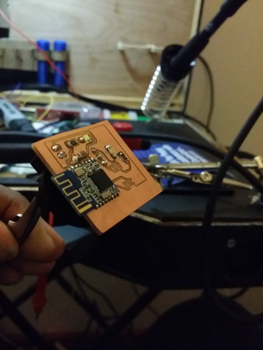
With that in mind, [sidsingh] has developed what we think is a very nice dedicated continuity tester. With a goal of using only parts on hand, he had to think small to fit everything into the case he had. So he started with a PIC10LF322 to support all the flavors of continuity testing he wanted to support. In addition to straight continuity, the tester can handle diode testing, detecting shorted or open diodes and even differentiating between regular and Schottky diodes. It also has an LED test mode and an interesting “discontinuity” testing mode — it only sounds its buzzer when continuity is broken. The video below shows that mode in action for finding intermittent cable faults, along with all the other modes.
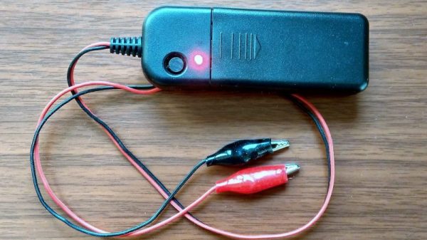
For an ostensibly single-purpose tool, this tester still manages to pack a lot of tests into one very compact package. Simpler continuity testers are good, too — check out this cheap dollar store build, or this slightly more complicated unit based on an ATtiny85.
Continue reading “Handy Continuity Tester Packs Multiple Modes Into A Tiny Package”