If you’ve ever tried to bend a metal pipe or bar over your knee, you’ll know that even lightweight stock requires quite a bit of force. And the force needs to be properly directed, lest the smooth bend you seek become a kink or a crease. When your hands and knees no longer fill the bill, try [MakeItExtreme]’s sturdy and simple roll bender.
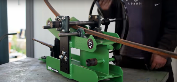
As we watched the video below, we had a little déjà vu — hadn’t the [MakeItExtreme] crew built a roll bender for their shop before? Turns out they had, but in reviewing that video, we can see why they gave it a second shot. This build is a model of simplicity compared to the previous. With a frame fabricated from just a few pieces of steel I-beam, this version is far more approachable than its big brother and just about as capable. The three forming rollers ride in stout pillow blocks and can be repositioned for different bending radii. A 2-ton hydraulic bottle jack provides the force needed to direct the stock through the rollers, which are manually powered. In a nice touch, the incomplete tool was used to create the rim of the large-diameter handwheel for the drive roller.
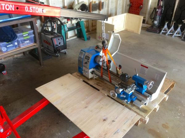
The tools keep piling up at [MakeItExtreme]’s open air workshop — we even get a glimpse of their heavy-lift electromagnet that we recently featured. As always, we love the fit and finish on these builds, and watching the time-lapse videos is like a condensed class in metalworking.
Continue reading “DIY Roll Bender Keeps It Simple And Sturdy”