Internet Of Tea: Coaster Watches For Optimum Drinking Temperature

Ah, the age-old question: at what temperature does one’s tea need to be for maximum enjoyment? It’s subjective, of course, but subjective in a way that makes everyone else’s opinion demonstrably wrong. What’s worse, the window of opportunity for optimum tea temperature is extremely narrow. What’s a tea drinker to do?

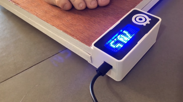
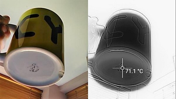
Throw a little technology at the problem, of course, in the form of this Internet of Tea smart coaster. Through careful experimentation, [Benjojo] determined the temperature of his favorite mug when the tea within was just right for drinking and designed a coaster to alert him to that fact. The coaster is 3D-printed and contains an MLX90616 IR temperature sensor looking up at the bottom of the mug. An ESP8266 lives inside the coaster too and watches for the Optimum Tea Window to open, sending an alert via Discord when the time is right. Yes, he admits that a simple blinking LED on the coaster would keep his tea habit metadata from being slurped up by the international tea intelligence community, but he claims he has nothing to hide. Good luck with that.

What’s next for [Dane]’s tea preparation? Perhaps he can close the loop and automate the whole pre-consumption process.

Programmable Badge Uses E-Ink And ESP8266

You’ve probably noticed that the hacker world is somewhat enamored with overly complex electronic event badges. Somewhere along the line, we went from using a piece of laminated paper on a lanyard to custom designed gadgets that pack in enough hardware that they could have passed for PDAs not that long ago. But what if there was a way to combine this love for weighing down one’s neck with silicon jewelry and the old school “Hello my name is…” stickers?

[Squaro Engineering] might have the solution with Badgy, their multi-function e-ink name…well, badge. Compatible with the Arduino SDK, it can serve as anything from a weather display to a remote for your smart home. Oh, and we suppose in an absolute emergency it could be used to avoid having to awkwardly introduce yourself to strangers.

Powered by an ESP-12F, Badgy features a 2.9″ 296×128 E-Ink display and a five-way tactical switch for user input. The default firmware includes support for WiFiManager and OTA updates to make uploading your own binaries as easy as possible, and a number of example Sketches are provided to show you the ropes. Powered by a LIR2450 3.6 V lithium-ion rechargeable coin cell, it can run for up to 35 days in deep sleep or around 5 hours of heavy usage.

Schematics, source code, and a Bill of Materials are all available under the MIT license if you want to try your hand at building your own, and assembled badges are available on Tindie. While it might not be as impressive as a retro computer hanging around your neck, it definitely looks like an interesting platform to hack on.

Why Have Only One Radio, When You Can Have Two?

There are a multitude of radio shields for the Arduino and similar platforms, but they so often only support one protocol, manufacturer, or frequency band. [Jan Gromeš] was vexed by this in a project he saw, so decided to create a shield capable of supporting multiple different types. And because more is so often better, he also gave it space for not one, but two different radio modules. He calls the resulting Swiss Army Knife of Arduino radio shields the Kite, and he’s shared everything needed for one on a hackaday.io page and a GitHub repository.

Supported so far are ESP8266 modules, HC-05 Bluetooth modules, RFM69 FSK/OOK modules, SX127x series LoRa modules including SX1272, SX1276 and SX1278, XBee modules (S2B), and he claims that more are in development. Since some of those operate in very similar frequency bands it would be interesting to note whether any adverse effects come from their use in close proximity. We suspect there won’t be because the protocols involved are designed to be resilient, but there is nothing like a real-world example to prove it.

This project is unique, so we’re struggling to find previous Hackaday features of analogous ones. We have however looked at an overview of choosing the right wireless tech.

ESP8266 Internet Controlled LED Dimmer

There’s no shortage of debate about the “Internet of Things”, largely centered on security and questions about how much anyone really needs to be able to turn on their porch light from the other side of the planet. But while many of us are still wrestling with the realistic application of IoT gadgets, there’s undoubtedly those among us who have found ways to put this technology to work for them.

One such IoT devotee is [Sasa Karanovic], who writes in to tell us about his very impressive custom IoT LED dimmer based on the ESP8266. Rather than rely on a commercial lighting controller, he’s designed his own hardware and software to meet his specific needs. With the LED strips now controllable by any device on his network, he’s started working on Python scripts which can detect what he’s doing on his computer and react accordingly. For example, if he’s watching a movie the lights will automatically dim, and come back up when he’s done.

[Sasa] has provided all the files necessary to follow in his footsteps, from the Gerber files for his PCB to the Arduino code he’s running on the ESP. The source code is especially worth checking out, as he’s worked in a lot of niceties that we don’t always see with DIY projects. From making sure the ESP8266 gets a resolvable DNS hostname on the network to using websockets which update all connected clients with status info in real-time, he’s really put a lot of work into making the experience as complete as possible.

He’s explains in his blog post what needs to be edited to put this code to work in your own environment, and there’s even some descriptive comments in the code and a helpful debug mode so you can see how everything works. It’s always a good idea to consider that somebody else down the road might be using your code; taking a few minutes to make things clear can save them hours of stumbling around in the dark.

If you need more inspiration for your ESP8266 lighting project, check out this ambient lighting controller for a kid’s room, or this professional under-cabinet lighting controller.

ESP8266 Zelda Heart Responds To Tweets

It might not be enough to make you the Hero of Time, but this piece of Hylian interactive art would still be a worthy addition to your game room. [Jeremy Cook] writes in to tell us about how he put together this 8-bit style heart display, and goes into enough detail on the hardware and software sides of things that you shouldn’t have any problem adapting his design for your own purposes.

The build is pretty simple overall but it does assume you have a CNC to cut the basic shape out of MDF. You could cut the shape by hand if you had to, but if you don’t have a CNC the next best thing might be to 3D print the case. You’d potentially have to print it in two parts right down the center though, depending on how big your bed is. Whichever way you create the case, you’ll then need to cut the shape out of a piece of acrylic to make the face.

In any event, once the pieces are cut out [Jeremy] adds in a Wemos D1 Mini, a power supply, and some red LED strips. He provides a wiring diagram, but it’s fairly straightforward stuff. With a couple of 2N2222 transistors he controls the LED strips right from the digital pins of the ESP8266.

The software side is setup to be controlled via IFTTT by way of Adafruit.io. When IFTTT sees one of the keywords on Twitter, it passes a message to Adafruit.io which ultimately talks to the ESP8266 and gets the heart going. The software supports three states (on, off, and half) and gives a good example of a basic IoT implementation on the ESP8266 if you’re looking for some inspiration.

This hack seems like it would fit in perfectly with the Zelda home automation project we covered last year.

Fail Of The Week: How Not To Make A 3D Scanner

Sometimes the best you can say about a project is, “Nice start.” That’s the case for this as-yet awful DIY 3D scanner, which can serve both as a launching point for further development and a lesson in what not to do.

Don’t get us wrong, we have plenty of respect for [bitluni] and for the fact that he posts his failures as well as his successes, like composite video and AM radio signals from an ESP32. He used an ESP8266 in this project, which actually uses two different sensors: an ultrasonic transducer, and a small time-of-flight laser chip. Each was mounted to a two-axis scanner built from hobby servos and 3D-printed parts. The pitch and yaw axes move the sensors through a hemisphere gathering data, but unfortunately, the Wemos D1 Mini lacks the RAM to render the complete point cloud from the raw points. That’s farmed out to a WebGL page. Initial results with the ultrasonic sensor were not great, and the TOF sensor left everything to be desired too. But [bitluni] stuck with it, and got a few results that at least make it look like he’s heading in the right direction.

We expect he’ll get this sorted out and come back with some better results, but in the meantime, we applaud his willingness to post this so that we can all benefit from his pain. He might want to check out the results from this polished and pricey LIDAR scanner for inspiration.

Continue reading “Fail Of The Week: How Not To Make A 3D Scanner”

Build A Wi-Fi Smart Scale

There are plenty of ways to monitor changes in your weight. You can get a vague idea from the fit of your pants or the notch on your belt. But anyone who’s serious about getting or staying in shape must step on the scale to get the cold, hard truth in pounds or kilograms.

Instead of just buying one, [igorfonseca83] decided to burn a few calories and build his own smart scale that uses IFTTT to send weight data to his fitness tracker. It’s made from four 50kg load cells that are sandwiched between two pieces of plywood. An HX711 sensor module reads the load cells, and a FireBeetle ESP8266 uploads the data to Adafruit IO. His weight is simultaneously displayed on a FireBeetle LED matrix.

We applaud [igorfonseca83]’s efforts to make this an easy, educational project that anyone can replicate. The instructions are great, the pictures are clear, and there’s even a CAD animation of all the pieces coming together. Jog past the break to see the build video, and weigh in down below.

Continue reading “Build A Wi-Fi Smart Scale”