Freq Out With LTSpice

We always enjoy [FesZ’s] videos, and his latest about FREQ function in LTSpice is no exception. In fact, LTSpice doesn’t document it, but it is part of the underlying Spice system. So, of course, you can figure it out or just watch the video below. The FREQ keyword allows you to change component attributes in a frequency-depended way.

Of course, capacitors and inductors are frequency dependent by design. But the FREQ technique allows you to adjust things like voltage sources or resistance in arbitrary ways. By default, you must specify the frequency response data in decibels, which isn’t always convenient. However, [FesZ] shows you how to use other methods to express them using modifiers to the command.

Continue reading “Freq Out With LTSpice”

Congratulations To Our Op-Amp Challenge Winners!

The real world is analog, and the op-amp is the indispensable building block of many analog circuits. We wanted to give you analog fanatics out there a chance to shine and to encourage our digital brothers and sisters to dip their toes in the murky waters where ones and zeroes define the ends of a spectrum rather than representing the only choice. Hence, we presented the Op Amp Challenge. And you did not disappoint!

We received 83 entries, and it was extraordinarily hard to pick the winners. But since we had three $150 DigiKey shopping sprees to give away, our six judges buckled down and picked their favorites. Whether or not you’ve got the Golden Rules of the ideal op-amp tattooed on your arm, you’ll enjoy looking through all of the projects here. But without further ado…

The Winners

[Craig]’s Op Art is an X-Y voltage generator to plug into an oscilloscope and make classic Lissajous and other spirograph-like images, and it’s all done in analog. Maybe it was his incredible documentation, the nice use of a classic three-op-amp tunable oscillator, or the pun hidden in the title. Whatever the case, it wowed our judges and picked up a deserved place in the top three.

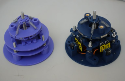
Hearkening back to the pre-digital dinosaur days, [Rainer Glaschick]’s Flexible Analog Computer is a modular analog computer prototyping system on a breadboard backplane. Since you have to re-wire up an analog computer for your particular, it’s great that [Rainer] gave us a bunch of examples on his website as well, including a lunar lander and classic Lorenz attractor demos.

And there was no way that [Chris]’s interactive analog LED wave array wouldn’t place in the top three. It’s a huge 2D analog simulation that runs entirely on op-amps, sensing when your hand moves across any part of its surface and radiating waves out from there. You have to admire the massive scale here, and you simply must check out the video of it in action. Glorious!

Continue reading “Congratulations To Our Op-Amp Challenge Winners!”

A Modular Analogue Computer

We are all used to modular construction in the analogue synth world, to the extent that there’s an accepted standard for it in EuroRack. But the same techniques are just as useful wherever else analogue circuits need to be configured on the fly, such as in an analogue computer. It’s something [Rainer Glaschick] has pursued, with his Flexible Analog Computer, an analogue computer made from a set of modules mounted on breadboard strips.

Standard modules are an adder and an integrator, with the adder also having inverter, comparator, and precision rectifier functions. The various functions can be easily configured by means of jumpers, and there are digital switches on board to enable or disable outputs and inputs. he’s set up a moon landing example to demonstrate the machine in practice.

We’re not going to pretend to be analogue computer experts here at Hackaday,but we naturally welcome any foray into analogue circuitry lest it become a lost art. If you’d like to experiment with analogue computing there are other projects out there to whet your appetite, and of course they don’t even need to be electronic.

Recreating An Analog TV Test Pattern

While most countries have switched to digital broadcasting, and most broadcasts themselves have programming on 24/7 now, it’s hard to remember the ancient times of analog broadcasts that would eventually stop sometime late at night, displaying a test pattern instead of infomercials or reruns of an old sitcom. They were useful for various technical reasons including calibrating the analog signals. Some test patterns were simply camera feeds of physical cards, but if you wanted the most accurate and reliable test patterns you’d need a Philips pattern generator which created the pattern with hardware instead, and you can build your own now because the designs for these devices were recently open-sourced. Continue reading “Recreating An Analog TV Test Pattern”

Op-Amp Challenge: A Logic-Free BCD

Of digital electronics, a wise man once said that “Every idiot can count to one.” Truer words have rarely been spoken, because at the end of the day, every digital circuit is really just an analog circuit with the interesting bits abstracted away. And to celebrate that way of looking at things, we’re pleased to present this BCD to seven-segment converter that uses no logic chips.

With cheap and easily available chips that perform this exact job, it might seem a little loopy to throw 20 LM324 op-amps at the job. But as [gschmidt958] explains, this is strictly for the challenge, plus it made a nice entry in the recently concluded Op-Amp Challenge contest. His work began in simulation, exploring op-amp versions of the basic logic gates — NAND, AND, OR, and NOT — all of which rely on using the LM324s as comparators. There were real-world curveballs, of course, not least of which was running out of the 10k resistors used for input averaging. Another plot twist was running out of time to order a PCB, which required designing one using MS Paint and etching it at home.

The demo video below shows the circuit at work, taking the BCD output of a 74HC393 counter — clocked by a 555, naturally — and driving a seven-segment LED.  It’s honestly a lot of work for such a simple task, but there’s something satisfying about the whole project. We think [Widlar] would be proud.

Continue reading “Op-Amp Challenge: A Logic-Free BCD”

Op-Amp Challenge: Get More From A Single Wire With An Analogue Adder

It’s been a running battle in some quarters for years, whether analog sensor processing is better than digital. Proponents of digital are sometimes driven by lack of familiarity with analog circuitry, while analog die-hards point to delays and software crashes in microcontrollers. We’d probably toe the line that a mixture of the two skills is best, but [paul] has gone full-on for the analog side with his position and limit sensor for a remote telescope. The ‘scope had only one control wire carrying a digital signal, so how was he to get extra information down it? The solution was to overlay a DC voltage, and use a summing network composed of a series of op-amps to encode position and limit data as voltage.

In operation, the circuit is a straightforward DC summing amplifier of the type that op-amps were designed for and at which they excel. We’re not so sure it needs the high-precision resistors and the choice of op-amps seems the wrong way round with the AD8532’s high current output being better suited to driving the line than straightforward summing, but we can see it does the job. If you’re after a demonstration of a DC summing amplifier using an op-amp, here’s your project. Meanwhile if you’re curious about an op-amp inside the black box, take a look at one of the simplest integrated circuit op-amps ever made.

MOSFET Heater Is Its Own Thermostat

While we might all be quick to grab a microcontroller and an appropriate sensor to solve some problem, gather data about a system, or control another piece of technology, there are some downsides with this method. Software has a lot of failure modes, and relying on it without any backups or redundancy can lead to problems. Often, a much more reliable way to solve a simple problem is with hardware. This heating circuit, for example, uses a MOSFET as a heating element and as its own temperature control.

The function of the circuit relies on a parasitic diode formed within the transistor itself, inherent in its construction. This diode is found in most power MOSFETs and conducts from the source to the drain. The key is that it conducts at a rate proportional to its temperature, so if the circuit is fed with AC, during the negative half of the voltage cycle this diode can be probed and used as a thermostat. In this build, it is controlled by a set of resistors attached to a voltage regulator, which turn the heater on if it hasn’t reached its threshold temperature yet.

In theory, these resistors could be replaced with potentiometers to allow for adjustable heat for certain applications, with plastic cutting and welding, temperature control for small biological systems, or heating other circuits as target applications for this type of analog circuitry. For more analog circuit design inspiration, though, you’ll want to take a look at some classic pieces of electronics literature.