Tearing Down A Digital Scope From ’78

If you’re a fan of vintage electronics and DIY tinkering, you’ll find this teardown by [Thomas Scherrer] fascinating. In a recent video, he delves into a rare piece of equipment: the Data Lab Transient Recorder DL 901. This device looks like a classic one-channel oscilloscope, complete with all the knobs and settings you’d expect.

The DL 901, made by Data Laboratories Ltd., is a mystery even to [Thomas], who couldn’t find any documentation online. From the DC offset and trigger settings to the sweep time controls, the DL 901 is equipped to handle slow, high-resolution analog-to-digital conversion. The circuitry includes TTL chips and a PMI DAAC 100, a 10-bit digital-to-analog converter. [Thomas] speculates it uses a successive approximation technique for analog-to-digital conversion—a perfect blend of analog finesse and digital processing for its time.

Despite its intriguing features, the DL 901 suffers from a non-responsive analog input system, limiting the teardown to a partial exploration. For those who enjoyed past Hackaday articles on oscilloscope teardowns and analog tech, this one is a treat. Watch the video to see more details and the full process of uncovering this vintage device’s secrets.

Continue reading “Tearing Down A Digital Scope From ’78”

Mechanical Logic Gates With Amplification

One of the hardest things about studying electricity, and by extension electronics, is that you generally can’t touch or see anything directly, and if you can you’re generally having a pretty bad day. For teaching something that’s almost always invisible, educators have come up with a number of analogies for helping students understand the inner workings of this mysterious phenomenon like the water analogy or mechanical analogs to electronic circuits. One of [Thomas]’s problems with most of these devices, though, is that they don’t have any amplification or “fan-out” capability like a real electronic circuit would. He’s solved that with a unique mechanical amplifier.

Digital logic circuits generally have input power and ground connections in addition to their logic connection points, so [Thomas]’s main breakthrough here is that the mechanical equivalent should as well. His uses a motor driving a shaft with a set of pulleys, each of which has a fixed string wrapped around the pulley. That string is attached to a second string which is controlled by an input. When the input is moved the string on the pulley moves as well but the pulley adds a considerable amount of power to to the output which can eventually be used to drive a much larger number of inputs. In electronics, the ability to drive a certain number of inputs from a single output is called “fan-out” and this device has an equivalent fan-out of around 10, meaning each output can drive ten inputs.

[Thomas] calls his invention capstan lever logic, presumably named after a type of winch used on sailing vessels. In this case, the capstan is the driven pulley system. The linked video shows him creating a number of equivalent circuits starting with an inverter and working his way up to a half adder and an RS flip-flop. While the amplifier pulley does take a minute to wrap one’s mind around, it really helps make the equivalent electronic circuit more intuitive. We’ve seen similar builds before as well which use pulleys to demonstrate electronic circuits, but in a slightly different manner than this build does.

Continue reading “Mechanical Logic Gates With Amplification”

A Simple 6DOF Hall Effect ‘Space’ Mouse

The 3DConnexion Space mouse is an interesting device but heavily patent-protected, of course. This seems to just egg people on to reproduce it using other technologies than the optical pickup system the original device uses. [John Crombie] had a crack at building one using linear Hall effect sensors and magnets as the detection mechanism to good — well — effect.

Using the SS49E linear Hall effect sensor in pairs on four sides of a square, the setup proves quite straightforward. Above the fixed sensor plate is a moveable magnet plate centred by a set of springs.  The magnets are aligned equidistant between each sensor pair such that each sensor will report an equal mid-range signal with zero mechanical displacement. With some simple maths, inputs due to displacements in-plane (i.e., left-right or up-down) can be resolved by looking at how pairs 
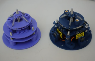
compare to each other. Rotations around the vertical axis are also determined in this manner.

Tilting inputs or vertical movements are resolved by looking at the absolute values of groups or all sensors. You can read more about this by looking at the project’s GitHub page, which also shows how the to assemble the device, with all the CAD sources for those who want to modify it. There’s also a detour to using 3D-printed flexures instead of springs, although that has yet to prove functional.

On the electronics and interfacing side of things, [John] utilises the Arduino pro micro for its copious analog inputs and USB functionality. A nice feature of this board is that it’s based on the ATMega32U4, which can quickly implement USB client devices, such as game controllers, keyboards, and mice. The USB controller has been tweaked by adjusting the USB PID and VID values to identify it as a SpaceMouse Pro Wireless operating in cabled mode. This tricks the 3DConnexion drivers, allowing all the integrations into CAD tools to work out of the box.

We do like Space Mouse projects. Here’s a fun one from last year, an interesting one using PCB coils and flexures, and a simple hack to interface an old serial-connected unit.


Open Source High Speed SiGe IC Production For Free!

We’ve covered the Tiny Tapeout project a few times on these pages, and while getting your digital IC design out there onto actual silicon for a low cost is super cool, it is still somewhat limited. Now, along comes the German FMD QNC project funding MPW (multi-project wafer) runs not in bog standard Silicon CMOS but Silicon-Germanium bipolar technology. And this is accessible to you and me, of course, provided you have the skills to design in this high-speed analog technology.

The design can be submitted via Github by cloning the IHP-Open-DesignLib repo, adding your design, and issuing a pull request. If your submission passes the correctness checks and is selected, it will be fabricated in-house by the IHP pilot line facility, which means it will take at least four months to complete.  However, there are a few restrictions. The design must be open source, DRC complete (obviously!) and below a somewhat limiting two square millimetres. Bonus points for selecting your project can be had for good documentation and a unique quality, i.e., they shouldn’t have too many similar designs in the project archive. Also, you don’t get to keep the silicon samples, but you may rent them for up to two years for evaluation. In fact, anybody can rent them.  Still, it’s a valuable service to trial a new technique or debug a design and a great way to learn and hone a craft that is difficult to get into by traditional means. Such projects would be an excellent source of verifiable CV experience points we reckon!

If you fancy getting your hands on your own silicon, but bipolar SiGe is a bit of a stretch, look no further than our guide to Tiny Tapeout. But don’t take our word for it—listen to the creator himself!

Hackaday Links Column Banner

Hackaday Links: July 7, 2024

Begun, the Spectrum Wars have. First, it was AM radio getting the shaft (last item) and being yanked out of cars for the supposed impossibility of peaceful coexistence with rolling broadband EMI generators EVs. That battle has gone back and forth for the last year or two here in the US, with lawmakers even getting involved at one point (first item) by threatening legislation to make terrestrial AM radio available in every car sold. We’re honestly not sure where it stands now in the US, but now the Swiss seem to be entering the fray a little up the dial by turning off all their analog FM broadcasts at the end of the year. This doesn’t seem to be related to interference — after all, no static at all — but more from the standpoint of reclaiming spectrum that’s no longer turning a profit. There are apparently very few analog FM receivers in use in Switzerland anymore, with everyone having switched to DAB+ or streaming to get their music fix, and keeping FM transmitters on the air isn’t cheap, so the numbers are just stacked against the analog stations. It’s hard to say if this is a portent of things to come in other parts of the world, but it certainly doesn’t bode well for the overall health of terrestrial broadcasting. “First they came for AM radio, and I did nothing because I’m not old enough to listen to AM radio. But then they came for analog FM radio, and when I lost my album-oriented classic rock station, I realized that I’m actually old enough for AM.”

Continue reading “Hackaday Links: July 7, 2024”

Clock Mixes Analog, Digital, Retrograde Displays

Unique clocks are a mainstay around here, and while plenty are “human readable” without any instruction, there are a few that take a bit of practice before someone can glean the current time from them. Word clocks are perhaps on the easier side of non-traditional displays but at the other end are binary clocks or even things like QR code clocks. To get the best of both worlds, though, multiple clock faces can be combined into one large display like this clock build from [imitche3].

The clock is actually three clocks in one. The first was inspired by a binary clock originally found in a kit, which has separate binary “digits” for hour, minute, and second and retains the MAX 7219 LED controller driving the display. A standard analog clock rests at the top, and a third clock called a retrograde clock sits at the bottom with three voltmeters that read out the time in steps. Everything is controlled by an Arduino Nano with the reliable DS3231 keeping track of time. The case can be laser-cut or 3D printed and [imitche3] has provided schematics for both options.

As far as clocks builds go, we always appreciate something which can be used to tell the time without needing any legends, codes, or specialized knowledge. Of course, if you want to take a more complex or difficult clock face some of the ones we’re partial to are this QR code clock which needs a piece of hardware to tell the time that probably already has its own clock on it.

Analog ASIC Design Built Using Digital Standard Cells

Tiny Tapeout is a way for students, hobbyists, and home gamers to get their own ASICs designs fabbed into real custom chips. Tiny Tapeout 3 was the third running, with designs mandated to be made up of simple digital standard cells. Only, a guy by the name of [Harald Pretl] found a way to make an analog circuit using these digital cells anyway.

In a video on YouTube, [Harald] gave an interview on how he was able to create a temperature sensor within the constraints of the Tiny Tapeout 3 requirements. The sensor has a range of -30 C to 120 C, albeit in a relatively crude resolution of 5 degrees C. The sensor works by timing the discharge of a pre-charged parasitic capacitor, with the discharge current being the subthreshold current of a MOSFET, which is highly dependent on temperature.  [Harald] goes deep into the details on how the design achieves its full functionality using the pre-defined digital cells available in the Tiny Tapeout 3 production run.

You can checkout a deeper breakdown of [Harald]’s design on the submission page. Meanwhile, Tiny Tapeout creator [Matt Venn] gave a great talk on the technology at Hackaday Supercon last year.

Continue reading “Analog ASIC Design Built Using Digital Standard Cells”