Over the last few months, the internal struggles between the various founders of Arduino have come to a head. This began last November when Arduino SRL (the Italian version of an LLC) sued Arduino LLC for trademark infringement in Massachusetts District court. To assuage the hearts and minds of the maker community, Arduino SRL said they were the real Arduino by virtue of being the first ones to manufacture Arduino boards. A fork of the Arduino IDE by Arduino SRL – simply an update to the version number – was a ploy to further cement their position as the true developers of Arduino.
This is a mess, but not just for two organizations fighting over a trademark. If you’re selling Arduinos in your web store, which Arduino do you side with?
[Nate] from Sparkfun is answering that question with a non-answer.
Currently, Arduino SRL is the only source of Arduino Unos. Sparkfun will continue to buy Unos from SRL, but they’re not necessarily siding with Arduino SRL; people demand blue Arduinos with Italy silkscreened on the board, and Sparkfun is more than happy to supply these.
There are, however, questions about the future of Arduino hardware. The Arduino software stack will surely be around in a year, but anyone that will be purchasing thousands of little blue boards over the next year is understandably nervous.
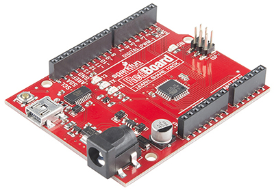 This isn’t the first time Sparkfun has faced a challenge in Arduino supply. In 2012, when the Arduino Uno R3 was released, all the documentation for their very popular Inventor’s Kit was obsoleted overnight. In response to these supply chain problems, Sparkfun created the RedBoard.
Sparkfun has always offered to pay royalties on the RedBoard to Arduino LLC, just as they do with the Arduino Pro and Pro Mini. Effectively, Sparkfun is on the fence, with offers to manufacture the Arduino Zero, Uno, Mega, and Due coming from the LLC.
The reason for this is consumers. If someone wants an Arduino SRL-manufactured board, they’ll buy it. If, however, a customer wants to support Arduino LLC, that option is on the table as well.
It’s not a pretty position to be in, but it does show how someone can support one Arduino over another. In a year or two, there will only be one Arduino, but until then, if you have a preference, at least Sparkfun is giving you a choice.
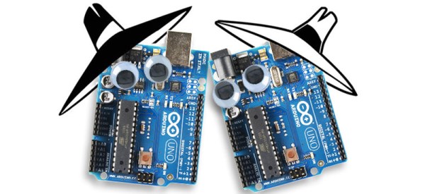
Credit to Sparkfun for the great Spy vs. Spy image. Why don’t you sell googly eyes?