[James] is designing an open-source 3D printed keyboard switch, with the end goal of building a keyboard with as many printed parts as possible. Since keyswitches are meant to be pressed quite often, the DIY switches ought to be tested just as rigorously as their commercial counterparts are at the factory. Maybe even more so.

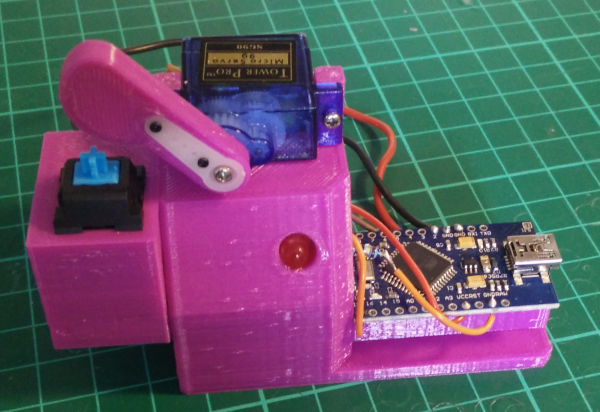
Rather than wear out his fingers with millions of actuations, [James] built a robot to test switches until they fail. All he has to do is plug a switch in, and the servo-driven finger slowly presses the slider down until the contacts close, which lights the LED.
The system waits 100ms for the contacts to stop any tiny vibrations before releasing the slider. That Arduino on the side tracks the contact and release points and sends them to the PC to be graphed. If the switch fails to actuate or release, the tester stops altogether.
We love that this auto-tester works just fine for commercial switches, too — the bit that holds the switch is separate and attaches with screws, so you could have one for every footprint variant. [James] recently did his first test of a printed switch and it survived an astonishing 13,907 presses before the printed coil spring snapped.
One could argue that this doubles as a servo tester. If you want a dedicated device for that, this one can test up to sixteen at a time.
Continue reading “Switch Tester Servo-Slaps Them ’til They Fail”