Arduinos have been the microcontroller platform of choice for nearly two decades now, essentially abstracting away a lot of the setup and lower-level functions of small microcontrollers in favor of sensible IDEs and ease-of-use. This has opened up affordable microcontrollers to people who might not be willing to spend hours or days buried in datasheets, but it has also obscured some of those useful lower-level functions. But if you want to dig into them, they’re still working underneath everything as [Jim] shows us in this last of a series of posts about interrupts.
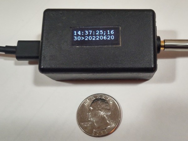
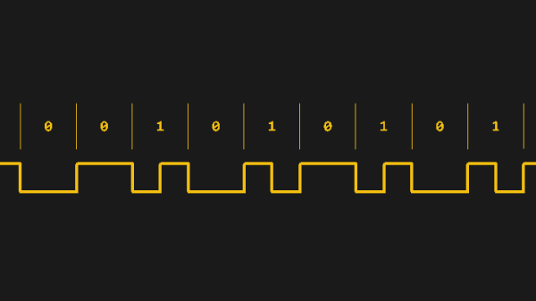
For this how-to, [Jim] is decoding linear timecodes (LTCs) at various speeds. This data is usually transmitted as audio, so the response from the microcontroller needs to be quick. To make sure the data is decoded properly, the first thing to set up is edge detection on the incoming signal. Since this is about using interrupts specifically, a single pin on the Arduino is dedicated to triggering an interrupt on these edges. The rest of the project involves setting up an interrupt service routine, detecting the clock signal, and then doing all of the processing necessary to display the received LTC on a small screen.
The project page goes into great detail about all of this, including all of the math that needs to be done to get it set up correctly. As far as general use of interrupts goes, it’s an excellent primer for using the lower-level functionality of these microcontrollers. And, if you’d like to see the other two projects preceding this one they can be found on the first feature about precision and accuracy, and the second feature about bitbanging the protocol itself.

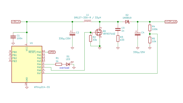
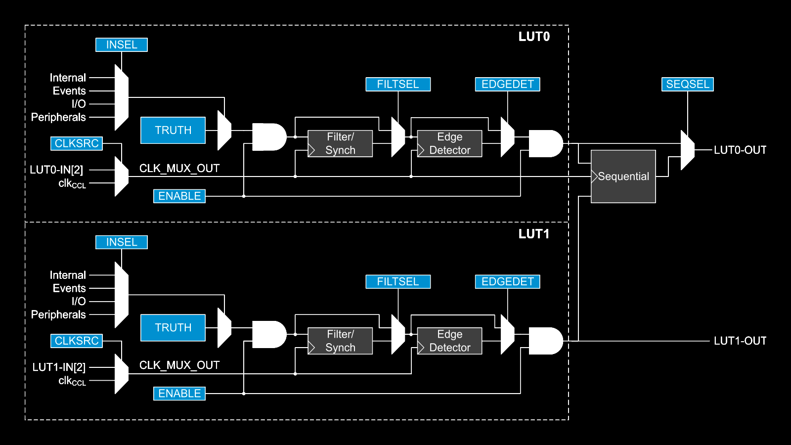
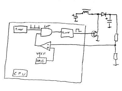 This napkinCAD sketch shows how [SM6VFZ] implemented the boost regulator in the ATtiny214. The AND gate is formed using one of the CCL LUT’s. The first “timer 1” on the left, connected to one input of the AND gate, is free running and set at 33 kHz. The analog comparator compares the boosted output voltage against an internally generated reference voltage derived from the DAC. The output of the comparator then “gates” timer 1 signal to trigger the second “timer 2” — which is a mono-shot timer set to max out at 15 us. This makes sure there is enough time left for the inductor to completely release its energy before the next cycle starts. You can check out the code that [SM6VFZ] used to built this prototype, and his generous amounts of commenting makes it easy to figure out how it works.