The toothed belt that turns the camshaft in synchronization with the crankshaft on many motor vehicle engines is something of an under-appreciated component. Unless you are unlucky enough to ave had one fail and destroy your engine, it’s probably something you’ve never given a second thought to outside of periodic service intervals.
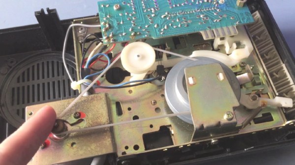
For something to perform such a task over so many thousands of miles of motoring it must be made of pretty strong stuff. Even when a belt is life-expired it is still in good physical shape, and [Crispyjones] saw the potential in a used Subaru belt to make a different type of belt. After keeping his engine in sync for so long it would serve no less vital a purpose, and keep his pants from falling down.
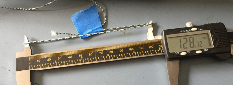
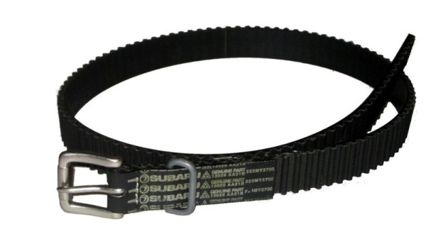
You can of course buy the hardware for a belt from a decent crafting store, but he chose to recycle a buckle from a worn-out leather belt. Cleaning the timing belt and cutting it carefully so that the Subaru logo would be on show to the outside world in the finished article, he secured it round the buckle with some epoxy glue and a bit of stitching. The original leather retaining loop is not really appropriate, so one is fashioned from wire. Finally we see the process for measuring where the holes should be placed, followed by their creation with a hole punch.
Hackaday isn’t a crafting site, so we don’t often feature projects like this one. But the humble timing belt is a component that we’ve probably all replaced and thrown away more than once without really thinking what the properties of the thing we’re throwing away are. So we like this relatively simple project for its re-use of something few of us would otherwise keep, as well as for its delivering rather a cool belt. We’ve featured plenty of cambelts here doing their traditional job, but this is the first time we’ve had one as an item of clothing. We’ll leave you with a glimpse of a future without cambelts at all.