Here’s a DEF CON talk that uses tools you likely have and it should be your next hacking adventure. In their Saturday morning talk [Mark Williams] and [Rob Stanely] walked through the process of adding their own custom code to a gaming mouse. The process is a crash course in altering a stock firmware binary while still retaining the original functionality.
The jumping off point for their work is the esports industry. The scope of esporting events has blown up in recent years. The International 2016 tournament drew 17,000 attendees with 5 million watching online. The prize pool of $20 million ($19 million of that crowdfunded through in-game purchases) is a big incentive to gain a competitive edge to win. Contestants are allowed to bring their own peripherals which begs the questions: can you alter a stock gaming mouse to do interesting things?
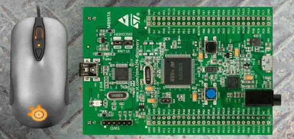
 The steelseries Sensei mouse was selected for the hack because it has an overpowered mircocontroller: the STM32F103CB. With 128 KB of flash the researchers guessed there would be enough extra room for them to add code. STM32 chips are programmed over ST-Link, which is available very inexpensively through the ST Discovery boards. They chose the STM32F4DISCOVERY which runs around $20.
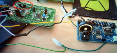
Perhaps the biggest leap in this project is that the firmware wasn’t read-protected. Once the data, clock, and ground pads on the underside of the board were connected to the Discovery board the firmware was easy to dump and the real fun began.
 They first looked through the binary for a large block of zero values signifying unused space in flash. The injected firmware is designed to enumerate as a USB keyboard, open Notepad, then type out, save, and execute a PowerShell script before throwing back to the stock firmware (ensuring the mouse would still function as a mouse). Basically, this builds a USB Rubber Ducky into stock mouse firmware.
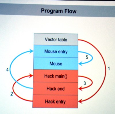
There are a few useful skills that make taking on this project a worthwhile learning experience. To compile your custom code correctly you need to choose the correct offset address for where it will end up once pasted into the firmware binary. The vector table of the original code must be rewritten to jump to the injected code first, and it will need to jump back to the mouse execution once it has run. The program flow on the left shows this. Both of these jumps require the program counter and registers to be saved and restored. The ARM stack is subtractive and the address will need to be updated to work with the added code.
The talk ended with a live demo that worked like a charm. You can check out the code in the MDHomeBrew repo. In this case the PowerShell script adds keyboard shortcuts for DOOM cheats. But like we said before, the experience of getting under the hood with the firmware binary is where the value will be for most people. With this success under your belt you can take on more difficult challenges like [Sprite_TM’s] gaming keyboard hack where the firmware couldn’t easily be dumped and an update binary was quite obsfucated.
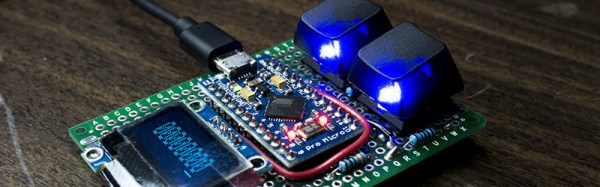
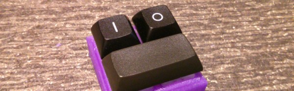
 No keyboard can be as high-end as the one you already have, your position in the hierarchy of text entry is assured. But then along comes [Chris Johnston] with his project, and suddenly your desktop looks very cluttered.