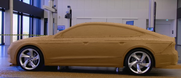
Mechanical Keyboard Is Also A Mouse

The mechanical keyboard community is a vibrant, if not fanatical, group of enthusiasts determined to find as many possible ways of assembling, building, and using as many high-quality keyboards as possible. With so many dedicated participants, most things that can be done with a keyboard already have been done. So when something as unique as this split keyboard that also doubles as a mouse pops up, we take notice.

The keyboard is a custom build from [Taliyah Huang] which uses a pair of Arduinos, one in each half of the keyboard, to communicate key and mouse information to a third Arduino which is plugged in to her laptop. The right-hand half of the keyboard also includes the circuitry from an optical mouse, which gets powered up when the caps lock button is held down. When activated, this allows the keyboard to be used as a mouse directly. It also includes support for most Mac gestures as well, making it just as useful as a trackpad.

While there were some problems with the design, including being slightly too tall to be ergonomic and taking nearly 24 hours of soldering to complete, the prototype device is an interesting one especially since it allows for full control of a computer without needing a dedicated mouse. For other unique mechanical keyboard concepts, we recently featured this build which takes design and functionality cues from the Commodore 64.

Continue reading “Mechanical Keyboard Is Also A Mouse”

A Medieval Gothic Monastery Built Using CAD / CAM

Just because you’re a monk doesn’t mean you can’t use CAD. The Carmelite monks of Wyoming are building a grandiose Gothic Monastery, and it’s awe inspiring how they are managing to build it.

The Carmelite monks needed a new, larger monastery to house their growing numbers, and found a parcel of land near Meeteetse Creek in Wyoming. The design of their new Gothic monastery was outsourced to an architectural firm. Gothic architecture is characterised by key architectural elements such as pointed arches, large stained glass windows, rib vaults, flying buttresses, pinnacles and spires, elaborate entry portals, and ornate decoration.

After some research, the monks settled on using Kansas Silverdale limestone for the monastery. Cutting and carving the elaborate stone pieces required for such a project, within time and cost constraints, could only be achieved using CNC machines. Hand carving was ruled out as it was a very slow process, would cost a whole lot more, and it wouldn’t be easy to find the artisans for the job. So when it came to shortlisting vendors for the vast amount of stone cutting and carving required for construction, the monks found themselves alarmed at how prohibitively expensive it would turn out to be.

Continue reading “A Medieval Gothic Monastery Built Using CAD / CAM”

Mouse Enjoys Its Freedom

Although it took a little while to standardize on the two-button-with-scroll-wheel setup, most computers have used a mouse or mouse-like device to point at objects on the screen since the 80s. But beyond the standard “point and click” features of the mouse, there have been very few ground-breaking innovations beyond creature comforts. At least, until the “Space Mushroom” mouse from [Shinsaku Hiura] hit our tips line.

This mouse throws away most of the features a typical mouse might have in favor of a joystick-like interface that gives it six degrees of freedom instead of the usual two — while still being about mouse-sized and held in the hand. It doesn’t even have a way of mapping motion directly to movements on the screen. Instead, it maps each degree of freedom to a similar movement of the mouse itself using these three joystick sensors physically linked together, with some underlying programming to translate each movement into the expected movement on the screen.

While this might not replace a standard mouse for every use case anytime soon, it does seem to have tremendous benefit in 3D modeling software, CAD, or anything where orienting a virtual object is the primary goal. Plus, since there’s no limit to the number of mice that can be attached to a computer (beyond USB limitations) this mouse could easily be used in conjunction with a normal mouse much like macro keyboards being used alongside traditional ones.

Continue reading “Mouse Enjoys Its Freedom”

Art of 3D printer in the middle of printing a Hackaday Jolly Wrencher logo

PrusaSlicer Now Imports STEP Files, Here’s Why That’s A Big Deal

PrusaSlicer has a new feature: the ability to import a CAD model for 3D printing. Starting in version 2.5.0-beta1, PrusaSlicer can import STEP format 3D models. An imported STEP file is converted to a triangle mesh on import (making it much like a typical .stl or .3mf file) which means that slicing all happens as one would normally expect. This is pretty exciting news, because one is not normally able to drop a CAD format 3D model directly into a slicer. With this change, one can now drag .stp or .step files directly into PrusaSlicer for printing.

First, a brief recap. In the world of 3D models there are two basic kinds: meshes and CAD models. The two work very differently, especially when it comes to editing. 3D printing has a long history of using .stl files (which are meshes) but making engineering-type changes to such files is difficult. Altering the size of a thread or changing mounting holes in a CAD model is easy. On an STL, it is not. This leads to awkward workarounds when engineering-type changes are needed on STLs. STEP, on the other hand, is a format widely supported by CAD programs, and can now be understood by PrusaSlicer directly. Continue reading “PrusaSlicer Now Imports STEP Files, Here’s Why That’s A Big Deal”

Fusion 360 Logo

Local Simulation Feature To Be Removed From All Autodesk Fusion 360 Versions

The removal of features from Autodesk products would appear to be turning into something of a routine at this point, with the announced removal of local simulations the latest in this series. Previously Autodesk had severely cut down the features available with a Personal Use license, but these latest changes (effective September 6) affect even paying customers, no matter which tier.

While previously executed local simulations on designs will remain accessible, any updates to these simulations, as well as any new simulations will have to use Autodesk’s cloud-based solver. This includes the linear stress, modal frequencies, thermal, and thermal stress simulation types, with each type of simulation study costing a number of Cloud Tokens.

Solving a linear simulation should initially cost 0 tokens, but the other types between 3 – 6 tokens, with the exact cost per token likely to vary per region. This means that instead of solving simulations for free on one’s own hardware, the only option in a matter of weeks will be solely through Autodesk’s cloud-based offerings.

Naturally, we can see this change going over exceedingly well with Fusion 360 users and we’re looking forward to seeing how Autodesk will spin the inevitable backlash.

(Thanks, [Jeremy Herbert] for the tip)

Adding Perlin Noise To 3D Printed Parts, With Python

Want to add a bit of visual flair to 3D printed parts that goes maybe a little more than skin-deep? That’s exactly what [volzo] was after, which led him to create a Python script capable of generating a chunk of Perlin noise, rendered as an STL file. What does that look like? An unpredictably-random landscape of hills and valleys.

The script can give printed parts a more appealing finish.

The idea is to modify a 3D model with the results of the script, leaving one with something a bit more interesting than a boring, flat surface. [volzo] explains how to use OpenSCAD to do exactly that, but it’s also possible to import the STL file the script creates into the CAD program of one’s choice and make the modifications there with some boolean operations.

If the effect looks a bit bit familiar, it’s likely because he used the method to design part of the 3D printed “toy” camera that we featured recently.

[volzo]’s method isn’t entirely plug and play, but it could still be a handy thing to keep in your back pocket when designing your next part. There are also other ways to modify the surfaces of prints for better aesthetics; we’ve previously covered velocity painting (also known as ‘tattooing’ in some slicers) and also fuzzy skin.

Perlin noise was created by [Ken Perlin] in the early 80s while working on the original Tron movie as a way to help generate more realistic-looking textures. It still fulfills that artistic function in a variety of ways, even today.

The Surprisingly Manual Process Of Building Automotive Wire Harnesses

Even from the very earliest days of the automobile age, cars and trucks have been hybrids of mechanical and electrical design. For every piston sliding up and down in a cylinder, there’s a spark plug that needs to be fired at just the right time to make the engine work, and stepping on the brake pedal had better cause the brake lights to come on at the same time hydraulic pressure pinches the wheel rotors between the brake pads.

Without electrical connections, a useful motor vehicle is a practical impossibility. Even long before electricity started becoming the fuel of choice for vehicles, the wires that connect the computers, sensors, actuators, and indicators needed to run a vehicle’s systems were getting more and more complicated by the year. After the engine and the frame, a car’s wiring and electronics are its third most expensive component, and it’s estimated that by 2030, fully half of the average vehicle’s cost will be locked in its electrical system, up from 30% in 2010.

Making sure all those signals get where they’re going, and doing so in a safe and reliable way is the job of a vehicle’s wire harnesses, the bundles of wires that seemingly occupy every possible area of a modern car. The design and manufacturing of wire harnesses is a complex process that relies on specialized software, a degree of automation, and a surprising amount of people-power.

Continue reading “The Surprisingly Manual Process Of Building Automotive Wire Harnesses”