Upgrading A MIDI Controller With An FPGA

While the “M” in MIDI stands for “musical”, it’s possible to use this standard for other things as well. [s-ol] has been working on a VJ setup (mixing video instead of music) using various potentiometer-based hardware and MIDI to interface everything together. After becoming frustrated with drift in the potentiometers, he set out to outfit the entire rig with custom-built encoders.

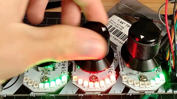
[s-ol] designed the rotary-encoder based boards around an FPGA. It monitors the encoder for changes, controls eight RGB LEDs per knob, and even does capacitive touch sensing on the aluminum knob itself. The FPGA communicates via SPI with an Arduino master controller which communicates to a PC using a serial interface. This is [s-ol]’s first time diving into an FPGA project and it looks like he hit it out of the park!.

Even if you’re not mixing video or music, these encoders might be useful to any project where a standard analog potentiometer isn’t accurate or precise enough, or if you just need something that can dial into a specific value quickly. Potentiometers fall short in many different ways, but if you don’t want to replace them you might modify potentiometers to suit your purposes.

Continue reading “Upgrading A MIDI Controller With An FPGA”

Divide To Conquer Capacitive Touch Problems

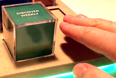
Back in the day, all of your music was on a shelf (or in milk crates) and the act of choosing what to listen to was a tangible one. [Michael Teeuw] appreciates the power of having music on demand, but misses that physical aspect when it comes time to “put something on”. His solution is a hardware controller that he calls MusicCubes.

Music cube makes selection using RFID, and touching to the right raises the volume level

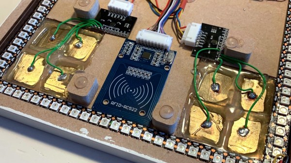
This is a multi-part project, but the most recent rework is what catches our eye. The system uses cubes with RFID tags in them for each album. This part of the controller works like a charm, just set the cube in a recessed part of the controller — like Superman’s crystals in his fortress of solitude — and the system knows you’ve made your decision. But the touch controls for volume didn’t work as well. Occasionally they would read a false touch, which ends up muting the system after an hour or so. His investigations led to the discovery that the capacitive touch plates themselves needed to be smaller.

Before resorting to a hardware fix, [Michael] tried to filter out the false positives in software. This was only somewhat successful so his next attempt was to cut the large touch pads into four plates, and only react when two plates register a press at one time.

He’s using an MPR121 capacitive touch sensor which has inputs for up to 12-keys so it was no problem to make this change work with the existing hardware. Surprisingly, once he had four pads for each sensor the false-positives completely stopped. The system is now rock-solid without the need to filter for two of this sub-pads being activated at once. Has anyone else experienced problems with large plates as the touch sensors? Can this be filtered easily or is [Michael’s] solution the common way to proceed? Share your own capacitive touch sensor tips in the comments below!

Want to get a look at the entire project? Start with step one, which includes a table of contents for the other build logs.

Creating A Touch Pad Without Dedicated Hardware

Year on year, microcontrollers and development platforms are shipping with ever-increasing feature sets. In the distant past, if you wanted an analog to digital converter or a PWM driver, you had to tack extra ICs on to your design. Nowadays, it’s all baked in at the factory. Of course, you may still find yourself working with a platform that lacks capacitive touch inputs. That’s no problem, though – you can do it all without dedicated hardware anyway!

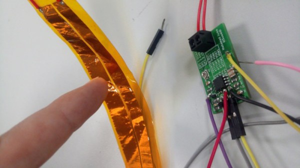
Capacitive touch sensing works by creating an RC oscillator, and allowing the user to affect the capacitance in the circuit through touch or proximity. By sensing the changes in the frequency of the oscillator, it’s possible to determine whether the object or pad is being touched or not. As the capacitance changes can be small, sometimes it’s desired to use a high frequency oscillator, and then pass the output through a frequency divider, which allows changes to be measured more easily by a slower microcontroller.

[Gabriel] does a great job of both explaining the theory involved, as well as presenting a practical way to achieve this with basic hardware. If you need to add touch sensitivity to an existing or otherwise limited platform, this is an easy way to go about doing it. There are definitely some interesting things you can do with the technology, after all.

Arduboy Goes Thin And Flexible For Portable Gaming

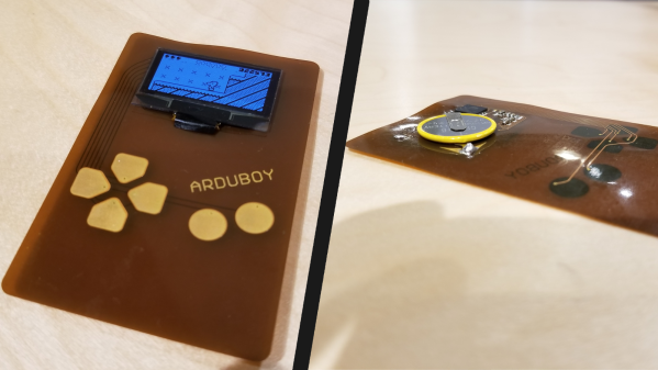
We all have a gaming system in our pocket or purse and some of us are probably reading on it right now. That pocket space is valuable so we have to budget what we keep in there and adding another gaming system is not in the cards, if it takes up too much space. [Kevin Bates] budgeted the smallest bit of pocket real estate for his full-size Arduboy clone, Arduflexboy. It is thin and conforms to his pocket because the custom PCB uses a flexible substrate and he has done away with the traditional tactile buttons.

Won’t a flexible system be hard to play? Yes. [Kevin] said it himself, and while we don’t disagree, a functional Arduboy on a flexible circuit makes up for practicality by being a neat manufacturing demonstration. This falls under the because-I-can category but the thought that went into it is also evident. All the components mount opposite the screen so it looks clean from the front and the components will not be subject to as much flexing and the inputs are in the same place as a traditional Arduboy.

cost = low, practicality = extremely low, customer service problems = high

     ~[Kevin Bates]

These flexible circuit boards use a polyimide substrate, the same stuff as Kapton tape, and ordering boards is getting cheaper so we can expect to see more of them popping up. Did we mention that we currently have a contest for flexible circuits? We have prizes that will make you sing, just for publishing your flex PCB concept.

Continue reading “Arduboy Goes Thin And Flexible For Portable Gaming”

Conductive Concrete Confounds Circuitry

There’s a fairly good chance you’ve never tried to embed electronics into a chunk of concrete. Truth be told, before this one arrived to us via the tip line, the thought had never even occurred to us. After all, the conditions electronic components would have to endure during the pouring and curing process sound like a perfect storm of terrible: wet, alkaline, and with a bunch of pulverized minerals thrown in for good measure.

But as it turns out, the biggest issue with embedding electronics into concrete is something that most people aren’t even aware of: concrete is conductive. Not very conductive, mind you, but enough to cause problems. This is exactly where [Adam Kumpf] of Makefast Workshop found himself while working on a concrete enclosure for a color-changing barometer called LightNudge.

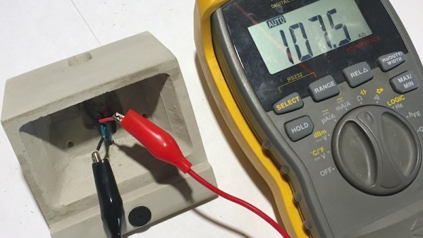
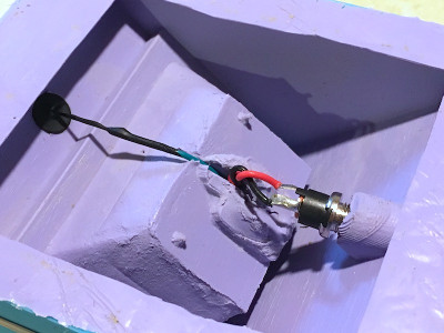
While putting a printed circuit board in the concrete was clearly not workable, [Adam] was hoping to simplify manufacturing of the device by embedding the DC power jack and capacitive touch sensor into the concrete itself. Unfortunately, [Adam] found that there was a resistance of about 200k Ohm between the touch sensor and the power jack; more than enough to mess with the sensitive measurements required for the touch sensor to function.

Even worse, the resistance of the concrete was found to change over time as the curing process continued, which can stretch out for weeks. With no reliable way to calibrate out the concrete’s internal conductivity, [Adam] needed a way to isolate his electronic components from the concrete itself.

Through trial and error, [Adam] eventually found a cheap method: dipping his sensor pad and wire into an acrylic enamel coating from the hardware store. It takes 24 hours to fully cure, and two coats to be sure no metal is exposed, but at least it’s an easy fix.

While the tip about concrete’s latent conductivity is interesting enough on its own, [Adam] also gives plenty of information about casting concrete parts which may be a useful bit of knowledge to store away for later. We have to admit, the final result is certainly much slicker than we would have expected.

This is the first one we’ve come across that’s embedded in concrete, but we’ve got no shortage of other capacitive touch projects if you’d like to get inspired.

Pumpkin Piano Promises A Gourd Time

Fall – it’s that time of year that brings falling leaves, Hallowe’en, and a pumpkin version of everything that you hold dear. In this case, it’s not a latte – it’s [Robert Vorthman]’s Pumpkin Piano.

[Robert] took a straightforward approach to the build, pressing a Raspberry Pi into service as the backbone of the operation. This is combined with an Adafruit breakout board for the MPR121, which is a chip that provides 12 capacitive touch-sensitive inputs. These are connected to the bountiful produce which make up the piano keys in this fun holiday hack. [Robert] uses some Python code that talks to fluidsynth, a software synthesizer that uses Soundfont files to create different sounds. It’s all wrapped up with some Neopixels that flash when each vegetable is triggered.

The build would make a great party piece for just about any fall gathering, and [Robert] has done a great job of rolling up all the hardware and software required in the write-up. For another take on a vegetable-based orchestra, check out last year’s Harpsi-gourd.

Hacking Touch Screens To Count Pulses

Heart rate sensors available for DIY use employ photoplethysmography which illuminates the skin and measures changes in light absorption. These sensors are cheap, however, the circuitry required to interface them to other devices is not. [Petteri Hyvärinen] is successfully investigating the use of capacitive touchscreens for heart rate sensing among other applications.

The capacitive sensor layer on modern-day devices has a grid of elements to detect touch. Typically there is an interfacing IC that translates the detected touches into filtered digital numbers that can be used by higher level applications. [optisimon] first figured out a way to obtain the raw data from a touch screen. [Petteri Hyvärinen] takes the next step by using a Python script to detect time variations in the data obtained. The refresh rate of the FT5x06 interface is adequate and the data is sent via an Arduino in 35-second chunks to the PC over a UART. The variations in the signal are very small, however, by averaging and then using the autocorrelation function, the signal was positively identified as a pulse.

A number of applications could benefit from this technique if the result can be replicated on other devices. Older devices could possibly be recycled to become low-cost medical equipment at a fraction of the cost. There is also the IoT side of things where the heart-rate response to media such as news, social media and videos could be used to classify content.

Check out our take on the original hack for capacitive touch imaging as well as using a piezoelectric sensor for the same application.