Chris Gammell Talks Circuit Toolboxes

Chris Gammell wants to know: What’s in your circuit toolbox?

Personally, mine is somewhat understocked. I do know that in one of my journals, probably from back in the 1980s, I scribbled down a schematic of a voltage multiplier I had just built, with the classic diode and capacitor ladder topology. I probably fed it from a small bell transformer, and I might have gotten a hundred volts or so out of it. I was so proud at the time that I wrote it down for posterity with the note, “I made this today!”

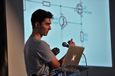
I think the whole point of Chris’ 2018 Hackaday Superconference talk is precisely what I was trying to get at when I made my “discovery” — we all have circuits that just work for us, and the more you have, the better. Most readers will recognize Chris from such venues as The Amp Hour, a weekly podcast he hosts with Dave Jones, and his KiCad tutorial videos. Chris has been in electrical engineering for nearly twenty years now, and he’s picked up a collection of go-to circuits that keep showing up in his designs and making life easier, which he graciously shared with the crowd.

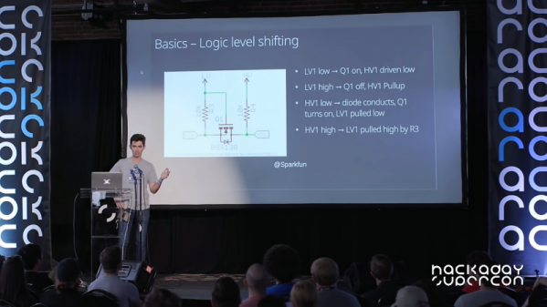
As Chris points out, it’s the little circuits that can make the difference. Slide after slide of his talk had schematics with no more than a handful of components in them, covering applications from dead-simple LED power indicators and switch debouncing to IO expansion using a 74HC595. And as any sensible engineer might, Chris’ toolbox includes a good selection of power protection circuits, everything from polarity reversal protection with a MOSFET and a zener to a neat little high-side driver shutoff using a differential amp and an optoisolator.

My favorite part of the talk was the “Codeless” section — things you can do with discrete components that make microcontroller circuits better. We see the “You could have used a 555!” comments from readers all the time, and Chris agrees, at least to a point. He aptly notes that microcontrollers can wake up with their IO pins in unknown states, and offered several circuits to keep the potential for mischief at bay, such as Schmitt trigger power-on reset or the simple addition of a pull-down resistor to default a MOSFET to a safe state. There’s a lot that code can accomplish, but adding just a few parts can make a circuit much safer and useful.

Chris acknowledges that in any audience, everyone is always at different places with regard to their hardware learning curve, so what’s old hat to someone might be a fresh revelation to another. Still, everything is new to someone at some point, and that’s often the best time to write it down. That’s what I did all those years ago with that voltage multiplier, and it never left me as a result. It’s good advice, and if you haven’t started building your own circuit toolbox, now’s the time.

Continue reading “Chris Gammell Talks Circuit Toolboxes”

The Embroidered Computer

By now we’ve all seen ways to manufacture your own PCBs. There are board shops who will do small orders for one-off projects, or you can try something like the toner transfer method if you want to get really adventurous. One thing we haven’t seen is a circuit board that’s stitched together, but that’s exactly what a group of people at a Vienna arts exhibition have done.

The circuit is stitched together on a sheet of fabric using traditional gold embroidery methods for the threads, which function as the circuit’s wires. The relays are made out of magnetic beads, and the entire circuit functions as a fully programmable, although relatively rudimentary, computer. Logic operations are possible, and a functional schematic of the circuit is also provided. Visitors to the expo can program the circuit and see it in operation in real-time.

While this circuit gives new meaning to the term “wearables”, it wasn’t intended to be worn although we can’t see why something like this couldn’t be made into a functional piece of clothing. The main goal was to explore some historic techniques of this type of embroidery, and explore the relationship we have with the technology that’s all around us. To that end, there have been plenty of other pieces of functional technology used as art recently as well, but of course this isn’t the first textile computing element to grace these pages.

Thanks to [Thinkerer] for the tip!


Agilent LCR Meter Teardown

Since 1999, one of the more popular manufacturers of test equipment has been Agilent, the spun-off former instrument division of Hewlett-Packard. From simple multimeters to fully-equipped oscilloscopes, they have been covering every corner of this particular market. And, with the help of [Kerry Wong] and his teardown of an Agilent LCR meter, we can also see that they’ve been making consistent upgrades to their equipment as well.

The particular meter that [Kerry] took apart was an Agilent U1731B, a capable LCR (inductance, capacitance, resistance) meter. He had needed one for himself and noted that while they’re expensive when new, they can be found at a bargain used, but that means dealing with older versions of hardware. For example, his meter uses an 8-bit ADC while the more recent U1733 series uses a 24-bit ADC. The other quality of this meter that [Kerry] made special note of was how densely populated the circuit board is, presumably to save on the design of a VLSI circuit.

While we don’t claim to stump for Agilent in any way, it’s good to know that newer releases of their equipment actually have improved hardware and aren’t just rebadged or firmware-upgraded versions of old hardware with a bigger price tag attached. Also, there wasn’t really any goal that [Kerry] had in mind besides sheer curiosity and a willingness to dive deep into electronics details, as those familiar with his other projects know already.

Open-source Circuit Simulation

For simple circuits, it’s easy enough to grab a breadboard and start putting it together. Breadboards make it easy to check your circuit for mistakes before soldering together a finished product. But if you have a more complicated circuit, or if you need to do response modeling or other math on your design before you start building, you’ll need circuit simulation software.

While it’s easy to get a trial version of something like OrCAD PSpice, this software doesn’t have all of the features available unless you’re willing to pony up some cash. Luckily, there’s a fully featured free and open source circuit simulation software called Qucs (Quite Universal Circuit Simulator), released under the GPL, that offers a decent alternative to other paid circuit simulators. Qucs runs its own software separate from SPICE since SPICE isn’t licensed for reuse.

Qucs has most of the components that you’ll need for professional-level circuit simulation as well as many different transistor models. For more details, the Qucs Wikipedia page lists all of the features available, as does the project’s FAQ page. If you’re new to the world of circuit simulation, we went over the basics of using SPICE in a recent Hack Chat.

Thanks to [Clovis] for the tip!

Print, Rinse, Wear. Nanowire Circuits For Your Microfibre Clothing.

While our bodies are pretty amazing, their dynamic nature makes integrating circuits into our clothing a frustrating process.  Squaring up against this challenge, a team of researchers from North Carolina State University have hit upon a potential boon for wearable electronics: silver nanowires capable of being printed on flexible, stretchy substrates.

It helps that the properties of silver nanowires lend themselves to the needs of wearable circuits — flexible and springy in their own right — but are not without complications. Silver nanowires tend to clog print nozzles during printing, so the research team enlarged the nozzle and suspended the nanowires in a water-soluble solvent, dramatically cutting the chance of clogging. Normally this would have a negative impact on precision, but the team employed electrostatic force to draw the ink to the desired location and maintain print resolution. Once printed, the solvent is rinsed away and the wearable circuit is ready for use.

By controlling print parameters — such as ink viscosity and concentration — the team are able to print on a wide variety of materials. Successful prototypes thus far include a glove with an integrated heating circuit and an electrocardiograph electrode, but otherwise the size of the printer is the only factor limiting the scale of the print. Until this technique becomes more widely available, interested parties might have to put their stock into more homebrew methods.

[Thanks for the tip, Qes!]

MicroPython Learns A New Trick – ISP For AVRs

One of the reasons why the Arduino became so popular was the ability to program it with ease. It meant the end of big parallel programmers that would cost an arm and a leg. The latest installment of CircuitPython from [Lady Ada] and the team over at Adafruit is a library for programming AVR microcontrollers without a dedicated PC.

For the uninitiated, in-system programming or ISP for AVR controllers employ the SPI bus to write the compiled binary to the flash memory of the controller. The discount on the number of pins used itself is a benefit though getting the timings right was a bit tricky in the good old days. Most dedicated ISPs handle this nicely, though they are normally slaves to a host PC where an ‘upload’ button initiates the process.

With CircuitPython (a derivative of MicroPython), programming microcontrollers does not require going through the code-compile-flash cycle. It can be run on a number of processors, however, AVRs are not among them so this neat little library offers the next best thing. Wire-up an Atmega328P or ATmega2560 to a board like the ESP8266 that does run CircuitPython, and you can write firmware on the fly.

There is a complete tutorial on the subject thanks to [Phillip Torrone] and [Lady Ada] which includes some demo files for testing out the functionality. This opens up a lot of possibilities where OTA firmware updates for an AVR co-processor. We expect to see some keychain AVR programmers in the near future taking a hint from the ESP8266 based Two-Factor Authentication featured previously.

Electromagnet-Powered Pendulum

We’re always happy to see hackers inspired to try something different by what they see on Hackaday. To [SimpleTronic] has a project that will let you stretch your analog electronics skills in a really fun way. It’s an electromagnet pendulum analog circuit. Whether you’re building it, or just studying the schematics, this is a fun way to brush up on the non-digital side of the craft.

The pendulum is a neodymium magnet on the head of a bolt, dangling on a one foot aluminium chain. Below, a Hall Effect sensor rests atop an electromagnet — 1″ in diameter, with 6/8″ wire coiled around another bolt. As the pendulum’s magnet accelerates towards the electromagnet’s core, the Hall effect sensor registers an increase in voltage. The voltage peaks as the pendulum passes overhead, and as soon as the Hall Effect sensor detects the drop in voltage, the electromagnet flicks on for a moment to propel the pendulum away. This circuit has a very low power consumption, as the electromagnet is only on for about 20ms!

The other major components are a LM358N op-amp, a CD4001B quad CMOS NOR gate, and IRFD-120 MOSFET. [SimpleTronic] even took the time to highlight each part of the schematic in order to work through a complete explanation.

Continue reading “Electromagnet-Powered Pendulum”