There’s something to be said for the feel of controls. Whether it’s the satisfying snap of a high-quality switch or the buttery touch of the pots on an expensive amplifier, the tactile experience of the controls you interact with says a lot about a device.
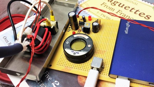
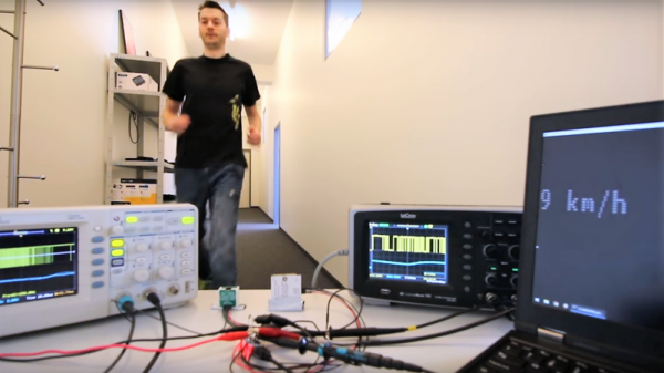
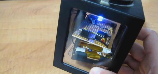
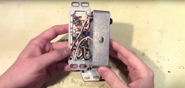
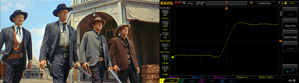
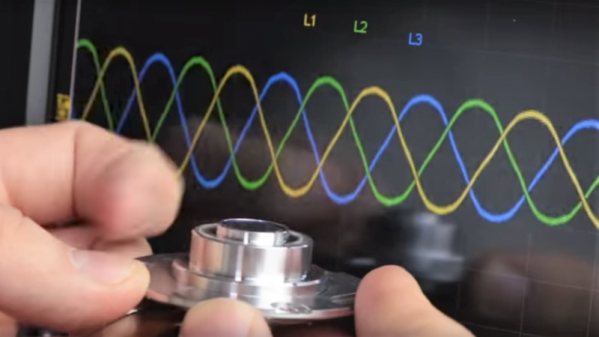
[GreatScott!] knows this, and rather than put up with the bump and grind of a cheap rotary encoder, he decided to find an alternative. He ended up exploring hard drive motors as encoders, and while the results aren’t exactly high resolution, he may be onto something. Starting with a teardown of some old HDDs — save those magnets! — [Scott!] found that the motors fell into either the four-lead or three-lead categories. Knowing that HDD motors are brushless DC motors, he reasoned that the four-lead motors had their three windings in Wye configuration with the neutral point brought out to an external connection. A little oscilloscope work showed the expected three-phase output when the motor hub was turned, with the leading and lagging phases changing as the direction of rotation was switched. Hooked to an Arduino, the motor made a workable encoder, later improved by sending each phase through a comparator and using digital inputs rather than using the Nano’s ADCs.
It looks like [GreatScott!]’s current setup only responds to a full rotation of the makeshift encoder, but we’d bet resolution could be improved. Perhaps this previous post on turning BLDC motors into encoders will help.
Continue reading “Scrap A Hard Drive, Build A Rotary Encoder”